
SMD Resistor Package Sizes: Ultimate Guide to Dimensions, Codes & Selection Strategies
Surface Mount Device (SMD) resistors are the backbone of modern electronic designs, and choosing the correct package size is a critical decision that directly impacts a PCB’s electrical performance, thermal reliability, manufacturing yield, and overall cost. Whether you’re designing a compact IoT sensor, a high-power industrial module, or an automotive electronics system, selecting the right SMD resistor package can mean the difference between a successful product and costly field failures.
In this comprehensive guide, you’ll find actionable, expert-backed information to simplify your SMD resistor selection process, including:
- A complete SMD resistor size chart (from 01005 to 2512) with precise dimensions, power ratings, and application use cases.
- Clear explanations of imperial and metric size codes to eliminate confusion during BOM creation and PCB design.
- Recommended PCB footprints and land pattern guidelines to prevent assembly defects like tombstoning and poor solder joints.
- Critical trade-offs between package size, power dissipation, assembly ease, and long-term reliability.
- Real-world examples for consumer electronics, IoT devices, automotive systems, and industrial circuits.
Complete SMD Resistor Size Chart (Imperial & Metric) for Quick Reference
| Package Code (Imperial) | Package Code (Metric) | Length (L) ± Tolerance | Width (W) ± Tolerance | Height (H) Typical | Power Rating (W) | Applications |
|---|---|---|---|---|---|---|
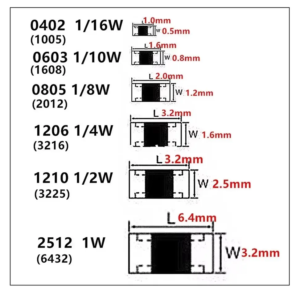
| 01005 | 0402 | 0.016″ / 0.40 mm | 0.008″ / 0.20 mm | 0.005″ / 0.13 mm | 0.031W (31/1000W) | Ultra-compact RF modules, wearable devices, miniature mobile components |
| 0201 | 0603 | 0.024″ / 0.60 mm | 0.012″ / 0.30 mm | 0.010″ / 0.25 mm | 0.05W (1/20W) | Smartphones, IoT sensors, compact logic circuits, portable electronics |
| 0402 | 1005 | 0.040″ / 1.00 mm | 0.020″ / 0.50 mm | 0.014″ / 0.35 mm | 0.062W (31/500W) | High-density PCBs, medical devices, wearable technology, small-form-factor designs |
| 0603 | 1608 | 0.060″ / 1.55 mm | 0.030″ / 0.85 mm | 0.018″ / 0.45 mm | 0.10W (1/10W) | Consumer electronics, signal conditioning, filtering circuits, general-purpose designs |
| 0805 | 2012 | 0.080″ / 2.00 mm | 0.050″ / 1.25 mm | 0.018″ / 0.45 mm | 0.125W (1/8W) | Industrial PCBs, LED drivers, embedded systems, moderate-power applications |
| 1206 | 3216 | 0.120″ / 3.10 mm | 0.060″ / 1.55 mm | 0.022″ / 0.55 mm | 0.25W (1/4W) | Automotive electronics, power monitoring circuits, high-reliability designs |
| 1210 | 3225 | 0.120″ / 3.10 mm | 0.100″ / 2.50 mm | 0.022″ / 0.55 mm | 0.33W (33/100W) | Power supplies, battery chargers, DC/DC converters, high-current paths |
| 1812 | 4532 | 0.180″ / 4.50 mm | 0.120″ / 3.20 mm | 0.024″ / 0.60 mm | 0.75W (3/4W) | High-power density circuits, motor control, power amplifiers, industrial modules |
| 2010 | 5025 | 0.200″ / 5.00 mm | 0.100″ / 2.50 mm | 0.024″ / 0.60 mm | 0.50W (1/2W) | Regulation circuits, industrial control modules, precision load applications |
| 2512 | 6332 | 0.250″ / 6.35 mm | 0.120″ / 3.20 mm | 0.024″ / 0.60 mm | 1.0W (1/1W) | Power systems, high-current paths, motor drivers, heavy-duty industrial applications |
Why This SMD Resistor Size Chart Matters: This chart eliminates guesswork during design, helping you select a package that balances size, power, and manufacturability. Smaller packages (01005–0402) save space but have lower power ratings and higher assembly complexity, while larger packages (0805+) offer better thermal performance and reliability but require more PCB real estate.
Understanding SMD Resistor Size Codes: Imperial vs Metric Standards
One of the most common sources of confusion for engineers is navigating SMD resistor size codes—specifically, the difference between imperial (EIA) and metric (IEC) systems. Misunderstanding these codes can lead to incorrect component procurement, footprint mismatches, and costly assembly defects. Below is a clear breakdown of both systems and how to avoid common pitfalls.
What is the Imperial (EIA) Code?
The imperial coding system is the most widely used naming convention for SMD resistors, favored by component manufacturers, distributors, and PCB design software libraries (KiCad, Altium, Eagle) worldwide. Here’s how it works:
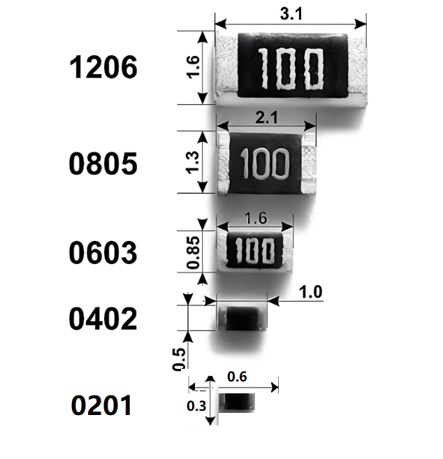
The 4-digit imperial code represents the resistor’s length and width in hundredths of an inch. For example:
- 0603 = 0.060″ (length) x 0.030″ (width)
- 0402 = 0.040″ (length) x 0.020″ (width)
- 0805 = 0.080″ (length) x 0.050″ (width)
Advantages of the imperial system:
- It’s the default labeling in most component datasheets (from manufacturers like Yageo, Vishay, Panasonic, and Samsung).
- It’s fully integrated into most PCB design tools and pick-and-place libraries.
- It’s universally recognized in the electronics industry, making cross-manufacturer compatibility easier.
Drawbacks of the imperial system:
- It does not include the resistor’s height, which varies by manufacturer and can impact PCB stacking.
- Tolerances for the same code can vary slightly between manufacturers, requiring verification with datasheets.
- Converting to millimeters (for international teams or metric-focused designs) is not intuitive.
What is the Metric (IEC) Code?
The metric (IEC) coding system is gaining popularity, especially in Europe and Japan, and is based on tenths of a millimeter. Like the imperial system, it uses a 4-digit code to represent length and width—but with a key difference in unit measurement.
Examples of metric codes and their corresponding dimensions:
- 1608 = 1.6 mm (length) x 0.8 mm (width) (matches imperial 0603)
- 1005 = 1.0 mm (length) x 0.5 mm (width) (matches imperial 0402)
- 2012 = 2.0 mm (length) x 1.2 mm (width) (matches imperial 0805)
Advantages of the metric system:
- It’s more precise and unit-consistent, using millimeters (the global standard for engineering).
- It aligns with IPC standards and many modern CAD tools for land pattern design.
- It eliminates confusion for international teams working across different measurement systems.
Critical Warning: Metric and imperial codes are not interchangeable. For example, an imperial 0402 is equivalent to a metric 1005—not a metric 0402 (which would incorrectly refer to a 0.4 mm x 0.2 mm resistor, a non-standard size). Mixing these codes on a BOM or in PCB design is a common mistake that leads to wrong parts, assembly delays, and wasted costs.
Manufacturer Tolerances to Consider
Even with standard size codes, actual dimensions can vary slightly between manufacturers. These tolerances impact pad size, solder mask openings, reflow profile behavior, and thermal dissipation. Always reference the component manufacturer’s datasheet for exact dimensions and tolerance ranges—never assume two “0603” resistors from different suppliers are identical.
Recommended PCB Footprints & Land Pattern Best Practices
Selecting the right SMD resistor package is only half the battle—designing a proper PCB footprint (land pattern) is equally critical. A poorly designed footprint can cause a host of assembly defects, including tombstoning, skewing, insufficient solder joints, and thermal imbalance—even with a perfectly chosen resistor.
SMD resistors rely entirely on solder joints for mechanical strength, electrical contact, and thermal conduction. An incorrect footprint can lead to weak joints, short circuits, or long-term reliability issues. Below are industry-aligned recommended footprints for the most common SMD resistor sizes, based on IPC-7351 standards (the global benchmark for PCB land patterns).
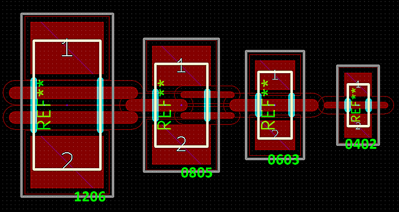
Key Footprint Guidelines for Common SMD Resistor Sizes
Note: These are default values for most applications. Always confirm with the resistor manufacturer’s datasheet for specific pad tolerances and recommendations.
0402 (1005 Metric) Footprint
- Pad length (A): 0.6 mm
- Pad width (B): 0.7 mm
- Pad-to-pad gap (C): 0.5 mm
- Overall land length (D): ~1.8 mm
- Critical Note: 0402 components are extremely small and prone to tombstoning. A symmetric footprint is mandatory to ensure equal thermal balance during reflow soldering.
0603 (1608 Metric) Footprint
- Pad length (A): 0.9 mm
- Pad width (B): 1.0 mm
- Pad-to-pad gap (C): 0.8 mm
- Overall land length (D): ~2.7 mm
- Critical Note: 0603 is the most widely used size in consumer electronics, offering a balance of size, manufacturability, and performance. It’s compatible with most automated SMT lines and is easy to rework.
0805 (2012 Metric) Footprint
- Pad length (A): 1.2 mm
- Pad width (B): 1.4 mm
- Pad-to-pad gap (C): 1.4 mm
- Overall land length (D): ~4.0 mm
- Critical Note: 0805 resistors tolerate more thermal stress and are easier to hand-solder than smaller packages. They’re ideal for moderate-power circuits and applications where reliability is a priority (e.g., industrial equipment).
1206 (3216 Metric) Footprint
- Pad length (A): 1.6 mm
- Pad width (B): 1.8 mm
- Pad-to-pad gap (C): 1.6 mm
- Overall land length (D): ~5.0 mm
- Critical Note: 1206 resistors excel at power dissipation and high-current applications. They’re easy to handle and inspect, making them a top choice for automotive and industrial designs.
How SMD Resistor Package Size Impacts PCB Performance (Electrical, Thermal, Mechanical)
The size of an SMD resistor directly influences three key aspects of PCB performance: electrical characteristics, thermal management, and mechanical strength. Understanding these impacts is critical to selecting a package that meets your design’s requirements.
Power Rating and Thermal Capacity
Power dissipation is directly tied to physical size: larger SMD resistors have more ceramic volume, thicker terminations, and a larger surface area, allowing them to dissipate heat more efficiently into the PCB. If a resistor is forced to dissipate more power than its rating allows, it will overheat, leading to resistance drift, accelerated aging, or even catastrophic failure.
Power Ratings by SMD Resistor Size (at 70°C ambient temperature):
- 01005: 0.031 W
- 0201: 0.05 W
- 0402: 0.063 W
- 0603: 0.10 W
- 0805: 0.125 W
- 1206: 0.25 W
- 1210: 0.33 W
- 1812/2010: 0.75 W
- 2512: 1.0 W
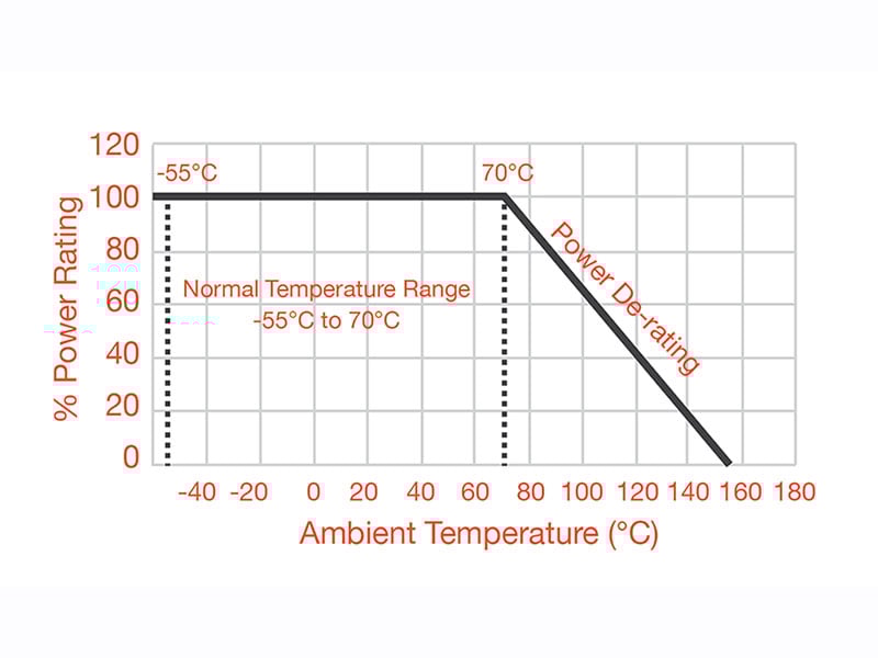
A critical note: All resistors require derating at temperatures above 70°C. Smaller packages derate more aggressively—for example, a 0402 resistor may only be able to handle 50% of its rated power at 100°C. This is why automotive and industrial designs (which operate at higher temperatures) often prefer 0805 and larger packages for power-intensive nodes.
Tolerance, Stability, and Noise Performance
Component size also impacts electrical precision. Ultra-small resistors (0201/0402) have minimal resistive film, making consistent deposition difficult during manufacturing. This leads to wider tolerances and lower stability compared to larger packages.
Tolerance by Package Size:
- 0201/0402: Typically ±5% (rarely available in tighter tolerances)
- 0603/0805: ±1–5% (available in precision grades)
- 1206+: Precision grades down to ±0.1% (ideal for analog and RF circuits)
Temperature Coefficient of Resistance (TCR) Stability:
- 0201/0402: 100–300 ppm/°C (higher drift)
- 0603–1206: 25–100 ppm/°C (moderate stability)
- Thin-film precision resistors (0603+): As low as 5 ppm/°C (high stability for critical applications)
Mechanical Strength and Stress Resistance
Mechanical robustness improves with package size. Small resistors (01005/0201/0402) have limited solder fillet volume and thinner ceramic bodies, making them vulnerable to flex cracking, vibration, and thermal shock. Larger packages (0805, 1206, 1210) offer superior resistance to board bending and harsh thermal cycling—critical for AEC-Q200 automotive compliance and industrial applications.
Pick-and-Place Reliability
Package size directly impacts SMT assembly yield:
- Ultra-small packages (01005/0201): Require advanced placement equipment and have higher tombstoning/misalignment rates. Only high-end SMT lines can handle these reliably, increasing assembly costs.
- Mid-sized packages (0603/0805): Offer the best balance of placement accuracy and reworkability, making them the industry standard for high-volume production.
- Larger packages (1206/2512): Easy to handle and inspect, but require well-balanced pad geometry to prevent shifting during reflow.
Manufacturing & Assembly Considerations for SMD Resistor Packages
Even the best-designed PCB can fail if the SMD resistor package is not compatible with your manufacturing process. Below are key assembly considerations to ensure high yield, low defect rates, and long-term reliability.
Pick-and-Place Machine Capability
Not all SMT lines can handle all package sizes. Before selecting a small package (01005/0201), confirm that your PCB manufacturer’s pick-and-place machines have the required accuracy (typically ±0.03 mm for ultra-small components). Most modern SMT lines handle 0402/0603/0805 with ease, but ultra-small packages may limit your manufacturing partners.
Solder Paste Stencil Aperture Guidelines
Solder paste deposition is critical for reliable soldering, and stencil aperture design varies by package size. Incorrect aperture size leads to skew, solder starvation, bridging, or tombstoning. Below are recommended stencil thicknesses for common package sizes:
| Package Size | Ideal Stencil Thickness |
|---|---|
| 01005 / 0201 | 80–100 µm |
| 0402 / 0603 | 100–120 µm |
| 0805+ | 120–150 µm |
Aperture Reduction: Reducing the stencil aperture by 5–10% prevents excess solder deposition, component float, bridging, and thermal imbalance—critical for small packages.
Assembly Yield Impact by Package Size
Package size directly affects assembly yield and cost. The table below summarizes the difficulty, defect risk, and cost impact of common sizes:
| Package Size | Assembly Difficulty | Defect Risk | Cost Impact |
|---|---|---|---|
| 01005/0201 | Very High | Extreme | High (higher assembly costs, lower yield) |
| 0402 | High | Moderate | Medium (slightly higher costs, manageable yield) |
| 0603 | Low | Low | Best (optimal yield, lowest cost) |
| 0805+ | Very Low | Very Low | High Reliability (slightly higher material costs, near-perfect yield) |
Industry Insight: Most professional engineers choose 0603 or 0805 for most designs, as they balance thermal stability, manufacturability, and cost.
Top Mistakes Engineers Make When Selecting SMD Resistors (And How to Fix Them)
Even experienced engineers make mistakes when selecting SMD resistor packages—often due to shortcuts during schematic design or a misunderstanding of how size impacts performance. Below are the most common mistakes and actionable fixes to avoid costly failures.
Mistake 1: Choosing a Smaller Package to Save PCB Space
One of the most frequent errors is downsizing a resistor (e.g., from 0603 to 0402) solely to reduce PCB area, without considering power dissipation or thermal performance. This often leads to overheating, resistance drift, and field failures.
Fix: Always calculate the actual power dissipation (P=I²R for current-driven circuits, P=V²/R for voltage-driven circuits) and choose a package that supports twice the calculated power. Check the resistor’s derating curve to ensure it can handle your PCB’s operating temperature.
Mistake 2: Ignoring Mechanical Strength and Package Height
Engineers often compare only footprint dimensions, ignoring the resistor’s height. Low-profile, small packages (0201/0402) are more prone to cracking, especially in applications with board bending (e.g., LED strips, long PCBs, automotive panels).
Fix: For mechanically stressed boards, use 0805 or 1206 packages. These offer thicker ceramic bodies and larger solder fillets, improving resistance to flexing and thermal shock.
Mistake 3: Using the Wrong PCB Footprint
Incorrect footprints cause more field failures than wrong resistor values. Using a generic footprint instead of following manufacturer-specific guidelines can lead to tombstoning, poor solder joints, and reliability issues.
Fix: Always reference the resistor manufacturer’s datasheet for footprint recommendations. Follow IPC-7351 standards and adjust pad sizes for manufacturer tolerances.
Mistake 4: Confusing Imperial and Metric Codes
Mixing imperial and metric codes on BOMs or in PCB design leads to incorrect part procurement, footprint mismatches, and assembly delays. For example, specifying “0402” without clarifying imperial vs metric can result in receiving a 01002 (non-standard) resistor instead of the intended 1005 metric.
Fix: Always list both imperial and metric codes in your BOM and CAD library (e.g., “0603 (1608 Metric)”). This eliminates confusion for procurement teams and manufacturers.
Step-by-Step Guide to Choosing the Right SMD Resistor Package for Your Project
Selecting the right SMD resistor package requires balancing five key factors: power dissipation, PCB space, electrical precision, mechanical reliability, and manufacturability. Follow these steps to make an informed decision.
Step 1: Calculate the Actual Power Requirement
First, determine how much power the resistor will dissipate. Use the appropriate formula based on your circuit type:
- Current-driven circuits (e.g., LED drivers): P = I²R (Power = Current² x Resistance)
- Voltage-driven circuits (e.g., voltage dividers): P = V²/R (Power = Voltage² / Resistance)
Choose a package with a power rating that is at least twice the calculated power to account for derating and thermal margin.
Step 2: Consider Temperature and Derating
All resistors derate (lose power-handling capacity) at temperatures above 70°C. Smaller packages derate more aggressively—for example, a 0402 resistor may only handle 0.03W at 100°C (half its rated 0.063W).
Rule of Thumb: If your PCB operates at 80–100°C (common in industrial/automotive designs), avoid running resistors close to their maximum rating. Go one size larger to ensure reliability.
Step 3: Evaluate PCB Space and Density
If compact size is a priority (e.g., IoT sensors, wearables), 0402 or 0603 may be necessary. For high-density PCBs, 0201 or 0402 can save space—but only if your manufacturer can handle them reliably. For most general-purpose designs, 0603 is the sweet spot between size and manufacturability.
Step 4: Determine Electrical Precision Requirements
For analog, RF, or precision circuits (e.g., medical devices, test equipment), prioritize larger packages (0603/0805) with tight tolerances (±1% or better) and low TCR (25–100 ppm/°C). Avoid 0402 or smaller packages for high-stability applications, as they have wider tolerances and higher drift.
Step 5: Assess Mechanical Reliability Needs
If your PCB will face vibration, shock, or bending (e.g., automotive, industrial equipment, portable devices), choose larger packages (0805/1206). These offer better mechanical strength and resistance to thermal cycling. For hand-soldered or reworked boards, 0603 and 0805 are easiest to handle.
How JKRGLO Support SMD Resistor Package Selection
Your PCB manufacturer’s capabilities play a critical role in selecting the right SMD resistor package. A reliable manufacturer will offer support to ensure your design is manufacturable, with high yield and low defects. Below are key ways professional PCB manufacturers assist with SMD resistor selection:
1. Extensive Component Library and Verified Stock
Top manufacturers maintain a large inventory of SMD resistors across all package sizes (0201 to 2512), ensuring availability and reducing lead times. They also verify component authenticity to avoid counterfeit parts, which can cause failures.
2. Advanced Pick-and-Place Capabilities
Professional SMT lines use high-speed, high-accuracy placement machines capable of reliably placing ultra-small packages (0201/01005) with minimal misalignment. This ensures high placement speed and low defect rates, even for complex designs.
3. Optimized Stencil and Reflow Profiles
Manufacturers fabricate laser-cut stencils with precise apertures tailored to each package size, following industry guidelines (80–100 µm for 0201, 100–120 µm for 0402/0603, 120–150 µm for larger packages). They also optimize reflow profiles to prevent tombstoning and ensure reliable solder joints.
4. PCB Fabrication Features for Reliable Resistor Mounting
High-quality PCB manufacturers offer features that support reliable SMD resistor mounting, including controlled solder mask registration, tight copper tolerances, high-quality ENIG/OSP finishes, and precise pad etching. These features reduce solder defects and improve long-term reliability.
5. DFM (Design for Manufacturability) Feedback
Professional manufacturers provide DFM analysis to identify potential issues with your PCB design, including footprint errors, package size incompatibilities, and thermal concerns. This feedback helps you adjust your design before production, saving time and money.
2026 SMD Resistor Package Trend: Miniaturization with Enhanced Reliability
As electronic devices become smaller and more powerful, the trend in 2026 is toward miniaturized SMD resistor packages with improved reliability. According to industry forecasts, 40% of consumer electronics and IoT devices will use 0402 or smaller packages by 2026, driven by demand for compact form factors. However, advancements in materials and manufacturing (e.g., improved thin-film technology, AI-optimized reflow profiles) are making these small packages more reliable than ever before.
Another key trend is the adoption of “environmentally friendly” SMD resistors, with lead-free and RoHS-compliant options becoming standard. Manufacturers are also developing resistors with higher power ratings in smaller footprints—for example, 0603 resistors with 0.15W ratings (up from 0.10W) to meet the needs of power-dense designs.
Conclusion
Selecting the right SMD resistor package is a critical step in ensuring your PCB’s performance, reliability, and manufacturability. By understanding the differences between imperial and metric codes, following footprint best practices, and balancing power, space, and reliability, you can avoid common mistakes and create a design that meets your project’s requirements.
Working with a professional PCB manufacturer is key—their expertise in component selection, SMT assembly, and DFM will help you optimize your design and achieve high yield. Whether you’re designing a compact IoT sensor or a high-reliability automotive module, the right SMD resistor package is the foundation of a successful product.
FAQs About SMD Resistor Package Sizes
1. What are the most common SMD resistor package sizes?
The most widely used SMD resistor packages are 0402, 0603, 0805, and 1206. 0603 is the industry standard for most consumer electronics, offering a balance of size, power, and manufacturability.
2. How do I identify an SMD resistor’s size on a PCB?
To identify an SMD resistor’s size:
- Measure the resistor’s length and width with a caliper.
- Cross-reference the measurements with an SMD resistor size chart (like the one in this guide).
- Check the PCB’s BOM or CAD design files for the package code.
3. Can I replace a larger SMD resistor with a smaller one?
You can replace a larger resistor with a smaller one only if the smaller package has a sufficient power rating and meets your precision requirements. For example, replacing a 0805 (0.125W) with a 0603 (0.10W) is possible only if the resistor’s actual power dissipation is ≤0.10W (accounting for derating).
About US
Founded in 2012, JKRGLO strives to build a one-stop platform for the electronic industry chain. By integrating PCB manufacturing, component procurement and PCB assembly services, we enable digital PCBA processing. With increasing investment in innovation and digital systems, we have achieved rapid growth and emerged as a leading PCB and PCBA manufacturer in the industry, capable of rapidly producing high-reliability and cost-effective products.