JKRGLO Advanced PCB Fab
ACCUEIL / Advanced PCB Fabrication
About Advanced PCB Fabrication
Advanced PCB Fabrication refers to high-precision, customized printed circuit board manufacturing services designed for high-end fields and demanding technical requirements. Different from standard PCBs, it adopts special substrate materials, sophisticated processes and strict parameter control to meet the high-performance needs of products in harsh or precision scenarios.
Our advanced PCB services integrate professional R&D support and strict quality management, providing reliable solutions for high-end electronic products that require high frequency, high temperature resistance, high precision and anti-interference.
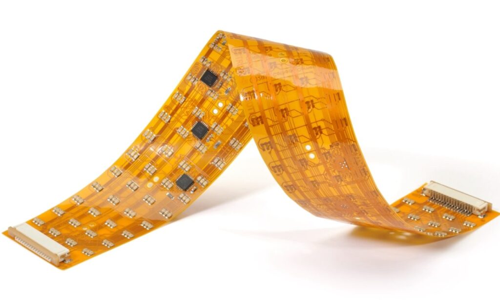
FLEXIBLE PRINTED CIRCUIT BOARDS
Flexible PCBs (FPCs) are crafted from flexible substrates like polyimide (PI), enabling bending and fitting into compact or curved spaces. Unlike rigid PCBs, FPCs adapt to product shapes (no need to design products around the board). Available in single-layer, multi-layer or dynamic flex designs, they support unique, lightweight electronic configurations and are ideal for space-saving modern devices.
BENEFITS
- Excellent resistance to temperature, chemicals, and radiation
- Lightweight and thin
- High reliability with fewer interconnects
- Compatible with diverse components and connectors
- Space-saving design
- Reduces packaging and material costs
- Minimizes assembly errors and repair needs
- Supports complex, dynamic applications
Flexible PCB Capability
| Fonctionnalité | Capacité |
| Catégorie de qualité | Norme IPC 2 |
| Nombre de couches | 1 - 8layers |
| Quantité commandée | 1pc - 10000+pcs |
| Durée de compilation | 2days - 5weeks |
| Matériau | DuPont PI, Domestic Shengyi PI |
| Dimensions de la planche | Min 6*6mm, Max 406*610mm |
| Épaisseur du panneau | 0.1mm - 0.8mm |
| Copper Weight (Finished) | 0,5 oz - 2,0 oz |
| Tracé/Espacement minimal | 3 mil/3 mil |
| Côtés du masque de soudure | Conformément au dossier |
| Couleur du masque de soudure | Vert, blanc, bleu, noir, rouge, jaune |
| Solder-stop coating---Soldermask oil | Vert, blanc, bleu, noir, rouge, jaune |
| Solder-stop coating---Coverlay | PI and PET film |
| Côtés sérigraphiés | Conformément au dossier |
| Couleur de la sérigraphie | White, Black, Yellow |
| Finition de surface | HASL - Hot air solder leveling |
| Lead - free HASL - RoHS | |
| ENIG - RoHS | |
| Étain pour immersion - RoHS | |
| OSP - RoHS | |
| Anneau annulaire Min | 4mil |
| Diamètre minimal du trou de forage | 8mil |
| Min. hole size---Drilling (PTH) | 0.2mil |
| Min. hole size---Punching (NPTH) | 0.5mil |
| Tolerance of dimension | ±0.05mm |
| Autres techniques | Peelable solder mask |
| Doigts d'or | |
| Stiffener (only for PI/FR4 substrate) |
RIGID-FLEX PRINTED CIRCUIT BOARDS
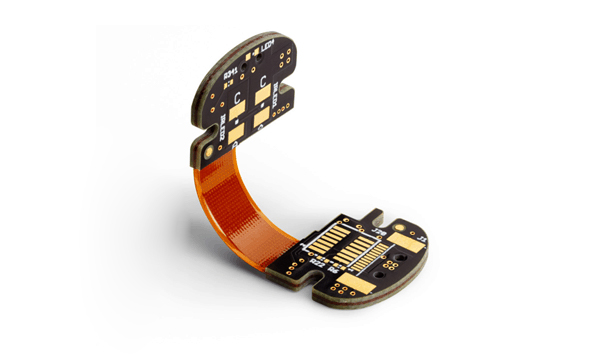
Rigid-flex PCBs combine the advantages of rigid and flexible PCBs, integrating flexible circuit sections with rigid board areas. These hybrid circuits feature multi-layer conductive layers separated by rigid/flexible insulation materials, with plated through-holes connecting all layers. The design supports 3D configurations, enabling bending while maintaining mechanical stability in key areas.
BENEFITS
- Ideal for dynamic bending and 3D assemblies
- High integration for complex designs
- Fewer connectors and solder joints for increased reliability
- Excellent performance in harsh environments
- Easy to test and maintain
- Improved product lifespan
- Space-saving and compact structure
- Supports high-density interconnects
Rigid-Flex PCB Capability
| Fonctionnalité | Capacité |
| Catégorie de qualité | Norme IPC 2 |
| Nombre de couches | 2 - 24layers |
| Quantité commandée | 1pc - 10000+pcs |
| Durée de compilation | 2days - 5weeks |
| Matériau | DuPont (PI25UM), FR4 |
| Dimensions de la planche | Min 6mm x 6mm / Max 457mm x 610mm |
| Épaisseur du panneau | 0.6mm - 5.0mm |
| Copper Weight (Finished) | 0,5 oz - 2,0 oz |
| Tracé/Espacement minimal | 3 mil/3 mil |
| Côtés du masque de soudure | Conformément au dossier |
| Couleur du masque de soudure | Vert, blanc, bleu, noir, rouge, jaune |
| Côtés sérigraphiés | Conformément au dossier |
| Couleur de la sérigraphie | White, Black, Yellow |
| Finition de surface | HASL - Hot air solder leveling |
| Lead - free HASL - RoHS | |
| ENIG - RoHS | |
| Anneau annulaire Min | 4mil |
| Diamètre minimal du trou de forage | 8mil |
| Impedance control | ±10% |
| Autres techniques | HDI |
| Doigts d'or | |
| Stiffener (only for PI/FR4 substrate) |
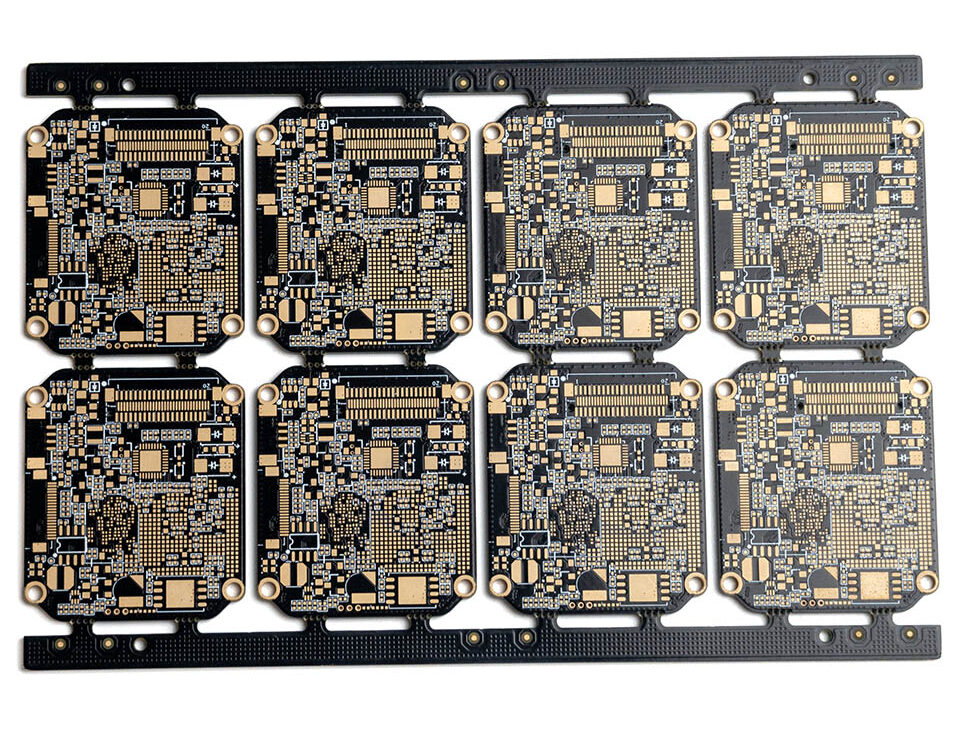
HIGH DENSITY INTERCONNECT (HDI) PRINTED CIRCUIT BOARDS
HDI PCBs boast higher wiring density, ideal for compact, high-performance electronic designs. With advanced technologies (microvias, blind vias, buried vias), they enable faster signal transmission, enhanced reliability and product miniaturization. Widely used in aerospace, military, telecommunications, consumer electronics and medical devices— the high-end industries demanding strict space, performance and precision standards.
BENEFITS
- Amélioration de l'intégrité du signal
- Higher Component & Connection Density
- Smaller Size, Lighter Weight
- Cost Optimization & Design Flexibility
- Greater Reliability & Thermal Performance
- Faster Time-to-Market
- Lower Inductance, Capacitance & EMI
Our Available HDI PCB Structures
| HDI Structures | Type of Micro vias | Mass Production | Small-Middle Batch | Prototype | Available |
| 1+N+1 | Blind vias | Yes | Yes | Yes | 4 layers+ |
| 2+N+2 | Blind/Buried staggered vias | Yes | Yes | Yes | 6 layers+ |
| 2+N+2 | Blind/Buried stacked vias | Yes | Yes | Yes | 6 layers+ |
| 3+N+3 | Blind/Buried staggered vias | / | Yes | Yes | 8 layers+ |
| 3+N+3 | Blind/Buried stacked vias | / | / | Yes | 8 layers+ |
HDI PCB Capability
| Fonctionnalité | Capacité |
| Catégorie de qualité | Norme IPC 2 |
| Nombre de couches | 4 - 24layers |
| Quantité commandée | 1pc - 10000+pcs |
| Durée de compilation | 2days - 5weeks |
| Matériau | FR4 standard Tg 140°C,FR4 High Tg 170°C, FR4 and Rogers combined lamination |
| Dimensions de la planche | Min 6*6mm / Max 457*610mm |
| Épaisseur du panneau | 0.4mm - 3.0mm |
| Copper Weight (Finished) | 0,5 oz - 2,0 oz |
| Tracé/Espacement minimal | 2.5mil/2.5mil |
| Côtés du masque de soudure | Conformément au dossier |
| Couleur du masque de soudure | Vert, blanc, bleu, noir, rouge, jaune |
| Côtés sérigraphiés | Conformément au dossier |
| Couleur de la sérigraphie | White, Black, Yellow |
| Finition de surface | HASL - Nivellement par soudure à l'air chaud |
| HASL sans plomb - RoHS | |
| ENIG - Nickelage chimique/dorure par immersion - RoHS | |
| Argent par immersion - RoHS | |
| Étain pour immersion - RoHS | |
| OSP - Organic Solderability Preservatives - RoHS | |
| Anneau annulaire Min | 4mil, 3mil - laser drill |
| Diamètre minimal du trou de forage | 6mil, 4mil - laser drill |
| Max Exponents of Blind/Buried Vias | stacked vias for 3 layers interconnected, staggered vias for 4 layers interconnected |
| Autres techniques | Flex-rigid combination |
| Via In Pad | |
| Buried Capacitor (only for Prototype PCB total area ≤1m²) |
ALUMINUM PRINTED CIRCUIT BOARDS
Aluminum PCBs (most common MCPCBs) are renowned for excellent thermal management. With an aluminum core, standard FR4 and a thermally conductive layer, they dissipate heat efficiently to boost component cooling and overall performance. Ideal for high-power, tight-tolerance applications—LED lighting, automotive systems, power electronics.
BENEFITS
- Efficient Thermal Dissipation
- High Reliability
- Improved Performance
- Power Handling
- Mechanical Durability
- Cost-Effective Solution
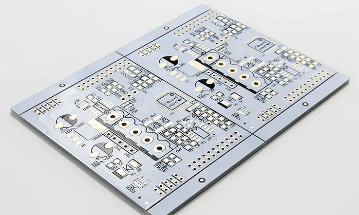
The able below features some of our aluminum core materials.
| Items | Performance Index (Measured value) |
| Peeling strength (n/mm) | 1.8 |
| Insulation resistance (ω) | >1*10 g |
| Breakdown voltage (vdc) | >2 k |
| Soakable soldering (°C/m) | 280°C / 260°C, 1 min, no bubble & delamination |
| Thermal conductivity (ω/m-k) | >0.8 |
| Thermal resistance (°C/ω) | < 1.2 |
| Combustibility | fv-o |
| Dielectric constant (1mhz) | 4 |
| Dielectric loss angle (tangent) | 0.03 |
Aluminum core PCB manufacturing capabilities
| Fonctionnalité | Capacité |
| Catégorie de qualité | Norme IPC 2 |
| Nombre de couches | 4 - 24layers |
| Quantité commandée | Quantité commandée |
| Durée de compilation | 2days - 5weeks |
| Matériau | Aluminum core (Domestic 1060), Copper core, FR4 covering |
| Dimensions de la planche | Min 6*6mm | Max 610*610mm |
| Épaisseur du panneau | 0.8mm - 5.0mm |
| Copper Weight (Finished) | 0.5oz - 10.0oz |
| Tracé/Espacement minimal | 4mil/4mil |
| Côtés du masque de soudure | Conformément au dossier |
| Couleur du masque de soudure | Vert, blanc, bleu, noir, rouge, jaune |
| Côtés sérigraphiés | Conformément au dossier |
| Couleur de la sérigraphie | White, Black, Yellow |
| Finition de surface | HASL - Nivellement par soudure à l'air chaud |
| HASL sans plomb - RoHS | |
| ENIG - Nickelage chimique/dorure par immersion - RoHS | |
| Anneau annulaire Min | 4mil |
| Diamètre minimal du trou de forage | 6mil |
| Autres techniques | Countersink holes |
| Screw holes |
HIGH FREQUENCY PRINTED CIRCUIT BOARDS
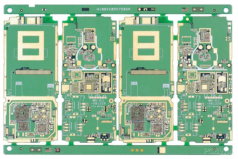
High Frequency PCBs are designed for high-speed, high-frequency signal transmission typically in the range
of 500MHz to 2GHz. These boards are essential for applications in RF (radio frequency), microwave, and
mobile communications, where signal integrity and transmission speed are critical. Unlike standard PCBs,
high-frequency boards require specialized materials like Rogers laminates to maintain stable electrical
performance and ensure minimal signal loss. Their design demands tight control over parameters such as
dielectric constant (Er), conductor width, and spacing, making precision fabrication crucial.
BENEFITS
- Faster Signal Transmission
- Amélioration de l'intégrité du signal
- Specialized Material Support
- High Customization & Flexibility
- Advanced Applications
- Reliable & Scalable Production
Commonly Used Materials for High-Frequency PCBs
| Matériau | Dielectric Constant |
| RO4350B | 3.48±0.05@10 GHz |
| RO4003C | 3.38±@10 GHz |
| Ro3003 | 3.00±0.04@10 GHz |
| Ro3010 | 10.2±0.03@10 GHz |
| RT5880 | 2.20±0.02@10 GHz |
High-Frequency PCB manufacturing capabilities
| Fonctionnalité | Capacité |
| Catégorie de qualité | Norme IPC 2 |
| Nombre de couches | 2 - 24layers |
| Quantité commandée | 1pc - 10000+pcs |
| Durée de compilation | 2days - 5weeks |
| Matériau | RO4003C, RO4350B, Ro3003, Ro3010, RT5880 |
| PP | Rogers 4450F, Domestic-(25FR), Domestic-(RF-27), Domestic-(6700) |
| Dimensions de la planche | Min 6mm x 6mm | Max 457mm x 610mm |
| Épaisseur du panneau | 0.4mm - 5.0mm |
| Copper Weight(Finished) | 0.5oz - 2.oz |
| Tracé/Espacement minimal | 3 mil/3 mil |
| Côtés du masque de soudure | Conformément au dossier |
| Couleur du masque de soudure | Vert, blanc, bleu, noir, rouge, jaune |
| Côtés sérigraphiés | Conformément au dossier |
| Couleur de la sérigraphie | White, Black, Yellow |
| Finition de surface | Electroless nickel/immersion gold (ENIG) - RoHS |
| Immersion silver - RoHS | |
| Immersion tin - RoHS | |
| Organic solderability preservatives - RoHS | |
| Anneau annulaire Min | 4mil |
| Diamètre minimal du trou de forage | 6mil |
| Tolérance d'impédance | ±10% |
| Autres techniques | Peelable solder mask |
| Doigts d'or | |
| Carbon oil | |
| Countersink holes |