
FR4 PCB
HOME / FR4 PCB
What is an FR4 PCB?
Flame Retardant 4, or FR4, is a material grade used in PCB manufacturing. It is made of fibreglass and “4” represents the UL94 V-0 flammability standard (it must self-extinguish after being ignited). Fibreglass reinforced woven glass fibre and epoxy resin with makes it excellent for electrically insulated applications. FR4 is a widely used material due to its low cost and high reliability.
FR4 Material Overview
FR4 represents flame-retardant grade 4 glass-reinforced epoxy laminate. The material’s dielectric constant and dissipation factor (loss tangent) are moderate. FR4 can be used in low-speed and high-power applications, making it the first choice for many hobbyists. This makes it suitable for general-purpose electronic designs. Dielectric constant: around 4.5 at 1MHz (moderate). Loss tangent: around 0.02 at 1MHz (moderate). The glass transition temperature (Tg) determines how the material behaves under heat. It is one of the most important thermal properties in the classification of FR4 materials.
Low Tg (130–140°C)
Standard Tg (150–160°C)
High Tg (>170°C)
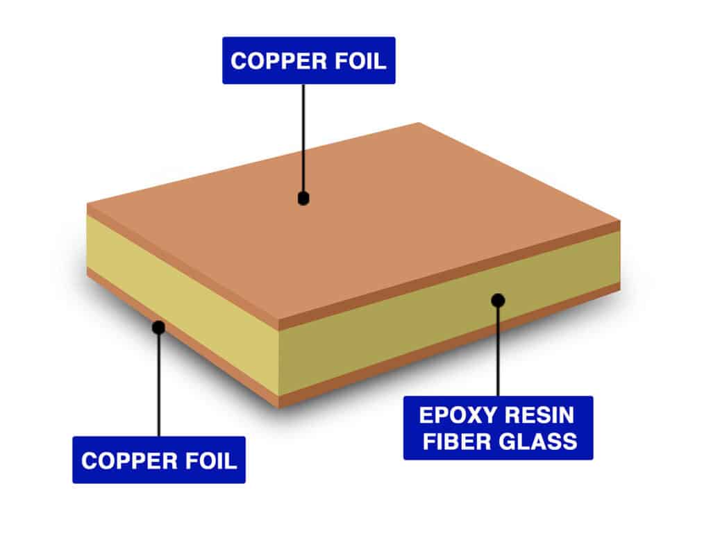
Structure and Properties of FR4
FR-4 is a composite material used as the substrate in PCBs. Its structure is made from:
Benefits of FR4 PCB Material
Cost-Effective and Widely Available
FR-4 is affordable compared to advanced laminates like Rogers. Its low cost makes it popular and the industry standard for most applications. It is globally available, making it easy to source for large production volumes.
Good Mechanical Strength
The woven fiberglass provides higher tensile strength, making it more resistant to warping, bending, and mechanical stress.
Reliable Electrical Insulation
Due to a moderate dielectric constant, it is excellent for low-frequency and higher-power applications. Additionally, the epoxy-fiberglass structure offers higher signal isolation.
Benefits of FR4 PCB Material
1. Signal Integrity and Impedance Control
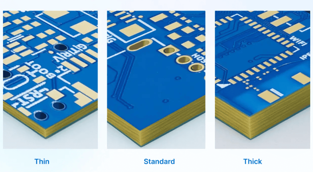
Thicker FR-4 increases the dielectric spacing, which raises impedance by introducing parasitic components. FR-4 thickness can be adjusted to control impedance for different circuit applications.
Thinner FR-4 has a smaller dielectric spacing between copper layers, which lowers the impedance of traces. However, the higher dielectric loss of FR-4 limits performance above a few GHz regardless of thickness.
2. Thermal Management
Thicker FR-4 offers improved heat spreading and higher thermal capacity, which helps reduce the risk of localized overheating.
Thinner FR-4 has limited heat-spreading capability on high-power boards, making it more susceptible to hot spots.
3. Mechanical Stability
Thicker boards are more rigid and resistant to bending, which makes FR4 more suitable for mechanically stressed assemblies.
Thinner boards are more flexible and lightweight, making them ideal for compact devices but more prone to warping.
Common Applications of FR4 PCBs
1. Consumer Electronics
FR4 PCBs balance cost and strength for everyday electronic devices. From smartphones to wearables, FR-4 provides durable and reliable PCB solutions.
2. Industrial Control Systems
Control systems, power supplies, and automation boards often use thicker FR-4 laminates. FR4 PCB for mechanical rigidity and ability to withstand moderate thermal cycling.
3. Automotive Electronics
Instrument clusters, infotainment units, and sensor modules frequently use FR-4 PCBs. FR4 PCBs provide stable performance under vibration and moderate heat.
JKRGLO FR4 PCB Manufacturing Capabilities
FR4 PCB Manufacturing Capabilities
| Features | Capabilities |
| Layer count | 1, 2, 4, 6, ...32 layers |
| Controlled Impedance | 4/6/8/10/12/14/16/18/20/.../32 layers |
| Impedance Tolerance | ±10% (±5Ω if value ≤ 50Ω) |
| Maximum Dimensions | 670 × 600mm (Thickness ≥ 0.8mm); |
| 500 × 600mm (Thickness < 0.8mm); | |
| 2-layer reaches 1020 × 600mm. | |
| Minimum Dimensions | 3 × 3mm; 70 × 70 for V-cut panel |
| Outer Copper Thickness | 1oz, 2oz (2.5oz, 3.5oz, 4.5oz for 2-layer) |
| Inner Copper Thickness | 0.5 oz, 1 oz, 2 oz |
| Surface finish | HASL (leaded / lead-free), ENIG(1u" / 2u") |
| Minimum Via Hole/Diameter | 0.15mm / 0.25mm |
| Hole Size Tolerance | ① Plated: Through-holes: +0.13 / -0.08mm ; Press-fit holes:±0.05mm |
| ② Non-plated: ±0.2mm | |
| Minimum Plated Slots | 0.5mm |
| Minimum Non-Plated Slots | 1.0mm |
| Plated Edges | Available with PCB size 10 × 10mm, thickness: 0.6mm. ENIG is required. |
| Blind Slot | Available in 2-32 layer boards with a thickness of ≥ 0.8mm. |
| Countersink Hole | Available in 2-32 layer boards with a thickness of ≥ 0.6mm. Supported countersink angle: 90°/135° |
| Backdrill | Available in 4-32 layer boards with a thickness of ≥ 0.8mm. Holes will be epoxy resin filled after backdrilling. |
| Castellated Holes | Available with PCB size 10 × 10mm. |
| Minimum Track Width and Spacing | ① 1oz: 0.10 / 0.10mm (4 / 4mil) for 1/2-layer ; 0.09 / 0.09mm (3.5 / 3.5mil) for muliti-layer |
| ② 2oz: 0.16 / 0.16mm (6.5 / 6.5mil) for 1/2-layer; 0.16 / 0.20mm (6.5 / 8mil) for multi-layer | |
| Minimum BGA Pad Diameter | 0.25mm |
| Gold Fingers Bevelling | 30° or 45° |
Why Choose JKRGLO FR4 PCBs?
Cost-Effective Production
FR4 PCBs from just $1. Equipped with professional production facilities, we manufacture up to 200,000 pieces per day.
Extensive Capability
Supports 1–32 layers, board thickness from 0.2mm to 3.2mm, and copper weights up to 3oz.
High Customization
Pick from 7 solder mask colors, multiple finishes, and copper thickness options to fit any project.
Fast & Global Delivery
Prototypes in as fast as 24 hours, shipped to over 200 countries worldwide.
Submit a FR4 PCB Quote Now
Frequently Asked Questions About FR4 PCB
What is the dielectric constant (Dk) of FR4 material?
FR4 typically has a dielectric constant of around 4.2–4.8 at 1 MHz. This property affects signal transmission speed and impedance control, making it an important factor in high-speed and RF designs.
What is the glass transition temperature (Tg) of FR4?
Standard FR4 has a Tg of about 130–140 °C, while high-Tg FR4 options can reach 170–180 °C or higher. Choosing the right Tg ensures PCB stability under high operating temperatures.
Is FR4 suitable for high-frequency circuits?
FR4 works well for most low- and mid-frequency applications. However, for RF or microwave circuits above ~1 GHz, specialized materials like Rogers or PTFE are recommended due to lower dielectric loss.
How does FR4 perform in multilayer PCB designs?
FR4 is widely used for multilayer PCBs (up to 40+ layers). Its insulating properties, mechanical strength, and cost-effectiveness make it a reliable choice for complex stack-ups.
Are FR4 PCBs RoHS compliant and environmentally safe?
Yes. Most modern FR4 laminates areRoHS- and REACH-compliant; halogen-free options are also available, supporting eco-friendly and sustainable electronics manufacturing.
How does PCB material FR4 compare with other PCB substrates?
Compared to high-frequency PCB materials like Rogers or PTFE, FR4 has higher dielectric loss but is far more cost-effective. For most standard applications, FR4 is the go-to option, while specialized materials are chosen for RF or microwave circuits.