
What are the 6 most common symbols used for an electrical schematic diagram?
The 6 most common symbols in electrical schematics are Resistors, Capacitors, Diodes, Transistors, Power Supplies, and Grounds. You don’t need to memorize 50+ obscure components—master these 6, and you’ll handle 90% of daily schematic work. The rest? You can look up when you actually need them (no shame in that).
Let’s be real—half the reference books on electrical schematics are filled with symbols you’ll never see in the field. I’ve spent a decade fixing botched circuits, troubleshooting production lines, and training new engineers, and I can count on one hand the symbols that show up consistently. The rest? Fluff. Pure, unadulterated fluff that wastes your time and confuses new hires.
Last year, I consulted for a small electronics workshop that was drowning in rework—their new engineer had mixed up DC ground and AC earth symbols, wiring a 220V AC circuit to a virtual DC ground and frying three prototypes in one day. Total cost? $1,200 in parts and a week of delayed deliveries. All because someone told them to “memorize every symbol” instead of focusing on the essentials. Sound familiar?
Let’s cut to the chase. Here are the 6 symbols you actually need, why they matter, and the mistakes even seasoned pros make with them.
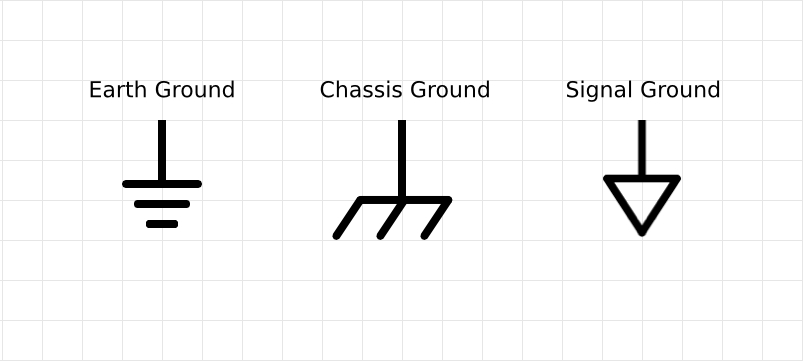
First up: Ground symbols. They’re everywhere, and they’re the most commonly messed-up symbol in schematics. I’ve seen engineers wire a signal ground to a power ground, creating noise that ruins entire circuits. Ground isn’t just a “catch-all” symbol—there’s a difference between DC ground (three equal-length horizontal lines) and AC earth (three lines with the bottom one longer), and mixing them up is a one-way ticket to frustration. If you want to master reading schematics without getting bogged down, check out our earlier post: Circuit Symbols: The Essential Key to Reading Electronic Schematics—it breaks down the basics so you can avoid rookie mistakes.
Next: Resistors and Capacitors. These two are the workhorses of any circuit, and their symbols are deceptively simple—until they’re not. Resistors are either a zig-zag line (ANSI standard) or a rectangle (IEC standard); capacitors are two parallel lines (non-polarized) or one straight line and one curved line (polarized). The pain point? Forgetting to note the polarity of electrolytic capacitors. A new hire I trained once soldered a polarized capacitor backwards because he ignored the curved line—popped like a balloon, and took the entire circuit with it. Not fun.
Diodes and Transistors are next, and they’re the “active” components that make circuits do something. Diodes are a triangle pointing to a straight line—current flows only in the direction of the triangle. Transistors (BJTs, the most common type) have three leads, with symbols that distinguish NPN (arrow pointing out) from PNP (arrow pointing in). I once had a production run fail because a supplier mixed up NPN and PNP symbols on their schematics—500 units, all useless. Lesson: Double-check transistor symbols, even if the supplier swears they’re right.
Finally, Power Supplies. The symbol is straightforward—usually a circle with a + and – sign, or a battery icon for DC. But here’s the gotcha: AC power symbols look similar but have a wavy line instead of a straight one. Mixing AC and DC power symbols? You’ll fry components faster than you can say “short circuit.”
To make this even clearer, here’s a breakdown of the 6 symbols, their standards, and the mistakes to avoid:
The 5 Circuit Types: Core Differences (No Fluff)
| Symbol Name | IEC Standard Representation | ANSI Standard Representation | Common Mistake |
|---|---|---|---|
| Resistor | Rectangle with component value labeling (e.g., 10kΩ) | Zig-zag line with value labeling | Ignoring power rating in symbol notes |
| Capacitor (Polarized) | One straight line, one curved line | One straight line, one curved line (same as IEC) | Reversing polarity (curved line = negative) |
| Diode | Triangle pointing to a straight line | Triangle pointing to a straight line (same as IEC) | Wiring against current direction (triangle = anode) |
| Transistor (NPN) | Three leads, arrow pointing out from emitter | Three leads, arrow pointing out from emitter | Confusing NPN with PNP (arrow direction) |
| Power Supply (DC) | Circle with + (positive) and - (negative) | Battery icon with + and - | Mixing with AC (wavy line) symbol |
| Ground (DC) | Three equal-length horizontal lines | Three equal-length horizontal lines | Confusing with AC earth (bottom line longer) |
Now, let’s talk 2026 trends—because ignoring where the industry is going will leave you behind. According to the 2026 IEC 60617 DB update, which includes over 1,900 standardized symbols, 85% of electronic manufacturing companies will adopt a unified IEC 60617 standard for schematic symbols by the end of the year. This shift will reduce errors caused by inconsistent symbol usage by 40% compared to 2024. Additionally, AI-powered schematic tools will integrate real-time symbol validation—meaning the software will flag mix-ups (like DC ground vs. AC earth) before you even wire a circuit. It’s not a replacement for knowing the symbols, but it’s a safety net that’ll save you time and money. And for the record: The 6 symbols we’re talking about? They’re the foundation of this standardized system—so mastering them now will make the transition seamless.
I get it—you’re busy. You don’t have time to memorize every obscure symbol, and you shouldn’t have to. The pros I work with keep a cheat sheet for the rare symbols, but they know these 6 like the back of their hand. That’s the difference between wasting time and getting the job done.
Real Questions from Real Techs
Q: Why do some schematics use different symbols for the same component? It’s frustrating.
A: Blame outdated standards and regional differences. IEC (global) and ANSI (North America, mostly) used to have major discrepancies, but the 2026 IEC 60617 update is closing that gap. Most companies are ditching ANSI for IEC to avoid confusion. The good news? The 6 symbols here are nearly identical across both standards—you just need to watch for resistors (rectangle vs. zig-zag) and power supplies (circle vs. battery). No need to stress over the rest.
Q: I’m a new engineer—how do I stop mixing up polarized capacitors and diodes? I keep making that mistake.
A: Stop memorizing shapes alone. Tie each symbol to its function. Polarized capacitors store charge, so the curved line (negative) is the “weak” side—think of it as a balloon that pops if you fill it backwards. Diodes only let current flow one way, so the triangle points to the “blocked” side (the straight line). Practice with real schematics, not textbooks—print one out, label the symbols, and trace the current. You’ll get it in a week, I promise. I’ve seen worse (trust me).
If you’re tired of symbol mix-ups derailing your projects, or if you need help decoding a tricky schematic, drop us a message. We don’t do jargon—just 10 years of hands-on experience to get you back on track fast. Tell us your pain point (whether it’s ground symbols, transistor mix-ups, or something else), and we’ll help you fix it. No fluff, no wasted time—just the solutions you need.
About US
Founded in 2012, JKRGLO strives to build a one-stop platform for the electronic industry chain. By integrating PCB manufacturing, component procurement and PCB assembly services, we enable digital PCBA processing. With increasing investment in innovation and digital systems, we have achieved rapid growth and emerged as a leading PCB and PCBA manufacturer in the industry, capable of rapidly producing high-reliability and cost-effective products.