Circuit Symbols: The Essential Key to Reading Electronic Schematics
Circuit symbols are the cornerstone of electrical and electronic diagrams, enabling the representation of complex circuits and components in a standardized, simplified format. These symbols are indispensable for engineers, electricians, and technicians, allowing them to understand circuit functions without relying on lengthy written documentation. Their universal recognition ensures consistent interpretation across different languages and regions, making them a vital tool for education, training, and professional collaboration.
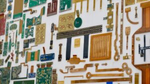
Circuit diagrams comprise a variety of components—including switches, capacitors, resistors, batteries, and transistors—connected by conductive nets or trails. Each component has a unique symbol that reflects its key characteristics and operational principles. Understanding how these components work is critical for effective circuit design, analysis, and troubleshooting. Familiarity with the properties of resistors, capacitors, and transistors, for example, allows engineers to predict component interactions, achieve desired circuit performance, and resolve issues efficiently.
How do the Circuit Symbols form the Circuit Diagram?
Electronic circuit symbols are concise drawings or pictograms that represent various components in a circuit’s schematic diagram. Most electrical elements feature two or more terminals, which are clearly depicted in their symbols to show how components connect to one another. Fundamental electrical and electronic symbols—such as the ground electrode, battery, resistor, and wire—form the building blocks of all circuit diagrams. With these basic symbols, anyone can sketch a clear, understandable electrical diagram.
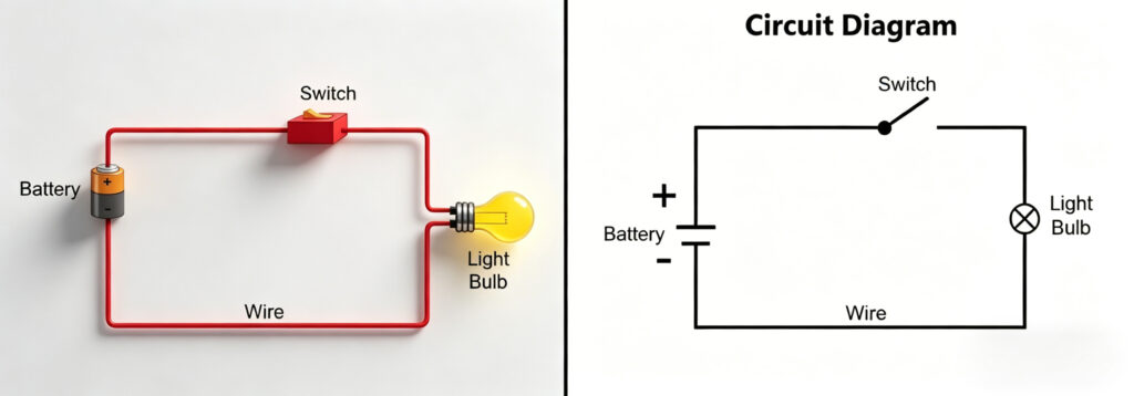
For example, a simple circuit consists of a battery, a switch, and a light bulb connected in a closed loop. While the same circuit can be presented in multiple formats, visual representations using symbols are far more intuitive. As the number of components in a circuit increases, the complexity of the diagram grows—but standardized symbols ensure the diagram remains readable. When undertaking a project involving circuit building or PCB design, understanding electronic symbols is a critical first step; the schematic layout is the foundation of PCB design, and without grasping the symbols within it, progress is often hindered.
Representing a Circuit with Symbols v/s Words
While words can effectively describe simple circuits, circuit diagrams using symbols offer distinct advantages. A circuit diagram with standardized symbols becomes self-explanatory, eliminating the need for lengthy text descriptions. For instance, the simple circuit mentioned earlier could be described as “a battery connected in series with a switch and a light bulb”—a straightforward explanation, but one that becomes cumbersome and ambiguous as circuits grow larger and more complex.
In contrast, circuit symbols allow for quick analysis of even the most intricate circuits. They simplify our understanding of circuit logic, save time, and reduce the risk of misinterpretation. In short, electronic symbols transform abstract circuit concepts into visual, easy-to-understand graphics, making them an essential tool for anyone working with electrical or electronic systems.
Advantages of the Circuit Symbols
The precise meaning of a circuit symbol is conveyed through details such as dots, lines, letters, letter spacing, shading, and numbers. Familiarity with the basic structure of these symbols is essential for understanding circuits and their functions. Below are the key advantages of using standardized circuit symbols:
- Reduces confusion in production: Using a defined set of electrical symbols eliminates the possibility of assigning different symbols to the same component, ensuring consistency in manufacturing.
- Lessens rework: A single, standardized set of symbols eliminates unnecessary and redundant schematic revisions, saving time and resources.
- Enhances electrical and mechanical communication: Standardized symbols reduce misunderstandings between MCAD (Mechanical Computer-Aided Design) and ECAD (Electronic Computer-Aided Design) teams. Linking 2D symbols to 3D modeled parts ensures all team members are aligned.
Saves time: Beyond reducing rework and misunderstandings, standardized symbols streamline the entire design, production, and maintenance process, allowing professionals to work more efficiently.
Physics Behind Designing of Symbols
Circuit symbols are designed to reflect the physical principles and operational characteristics of the components they represent. Understanding how a component works is the starting point for designing its symbol. Each symbol is crafted to convey the basic physics of the component, making it easier for professionals to grasp its function at a glance.
Most symbols follow international and national standards, including IEC (International Electrotechnical Commission), JIC (Joint Industry Council), ANSI (American National Standards Institute), and IEEE (Institute of Electrical and Electronics Engineers) standards. While these symbols are standardized, minor variations may exist between engineering disciplines due to historical traditions.
Examples illustrating the physics behind circuit symbols:
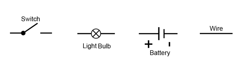
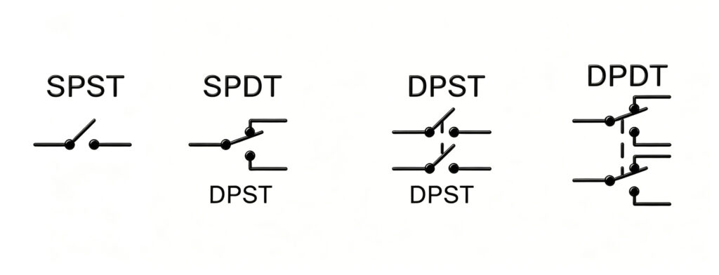
- Switch: The switch symbol depicts the open and closed states of a circuit, reflecting its core function of connecting or breaking the flow of current. This design is universally adopted for its simplicity and clarity.
- Light Bulb: A light bulb generates light by heating a resistive filament. Its symbol features a cross mark, representing the light emitted from this resistive source.
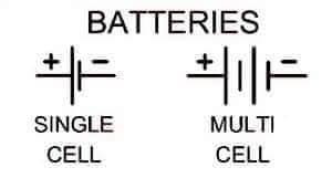
- Battery: A battery is an energy source composed of cells with a chemical electrolyte that provides polarity. Its symbol consists of two uneven parallel lines, with positive and negative polarity marks, reflecting the cell structure and polarity.
Wire: A wire is a low-resistance conductor used to connect components. Its symbol is a simple straight line, representing its role as a basic connection between devices.
More complex symbols require a deeper understanding of component physics, as their design directly reflects the component’s internal structure and function.
List of Circuit Diagram Symbols with Design Physics Behind it
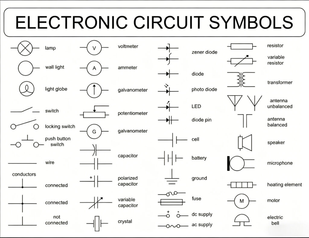
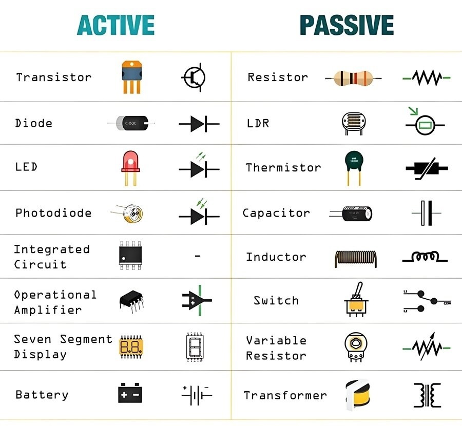
Circuit diagrams use standardized symbols to represent all components, ensuring consistency and readability. Every electrical or electronic component—from passive components like resistors and capacitors to active components like diodes and transistors—has a unique symbol. Below are the most commonly used electronic component symbols, along with the physics behind their design:
Passive Components
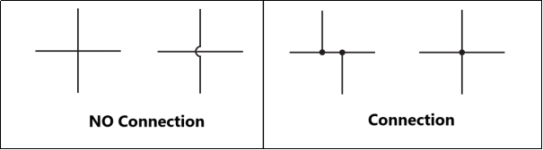
- Wires: Used to connect components, wires are represented by straight lines. Crossing wires without a dot indicate no connection (a crossover), while crossing wires with a dot indicate a connection.
- Switches: The switch symbol reflects its function of opening or closing a circuit, with designs that clearly show the two states. This universal symbol is easy to recognize and interpret.
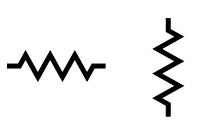
- Resistor: A resistor opposes the flow of current, so its symbol is a zigzag line—visually representing the “obstruction” to current flow. A variable resistor, which allows for adjustable resistance, adds an arrow in the middle of the zigzag line.
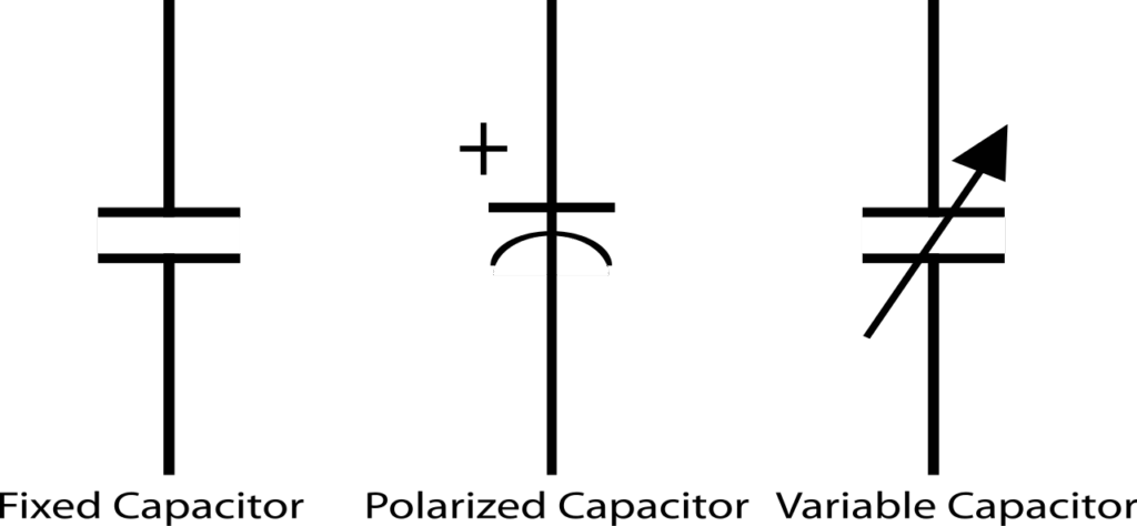
- Capacitor: Capacitors store electrical energy in the form of charge, with two internal plates for charge storage. Their symbol consists of two parallel bars separated by a small gap, reflecting this plate structure. Variable capacitors include an arrow, while polarized capacitors feature polarity marks (positive and negative).
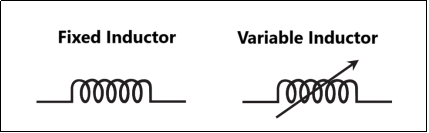
- Inductors: Inductors store energy in a magnetic field and have a coil-like structure. Their symbol is a series of loops, representing the coil and its magnetic field properties. Inductors are non-polar devices.
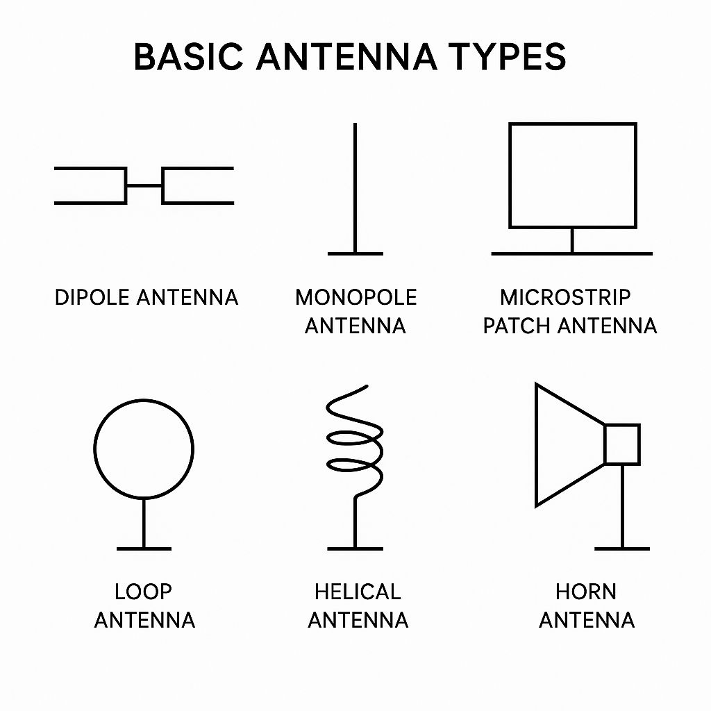
- Antenna: Antennas transmit and receive electromagnetic waves, a function reflected in their symbols. Common antenna symbols include wire and loop designs, corresponding to different antenna types used in RF electronics.
Power Symbols
- Battery: As an energy source made of cells, its symbol features two uneven parallel lines (representing cells) with polarity marks, reflecting its chemical structure and ability to provide a voltage difference.
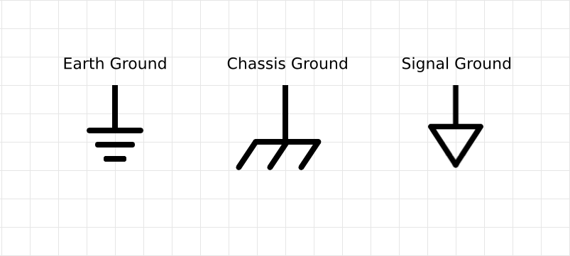
- Ground: The ground serves as a common reference point for voltage levels and a return path for current. Its symbol is designed to be easily recognizable, often featuring a series of horizontal lines of decreasing length.
- VDD: VDD represents the positive supply voltage for circuits, often used alongside a ground reference (GND). Its symbol is a label connected to the positive terminal of a battery, indicating its role as a power source.

Measuring Instruments
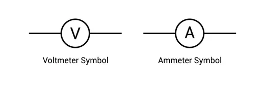
- Ammeter: Measures current in a circuit and is connected in series. Its symbol features the letter “A” (for amperes) within a circular shape, reflecting its function as a current-measuring device.
- Voltmeter: Measures voltage across components and is connected in parallel. Its symbol features the letter “V” (for volts) within a circular shape, indicating its role as a voltage-measuring device.
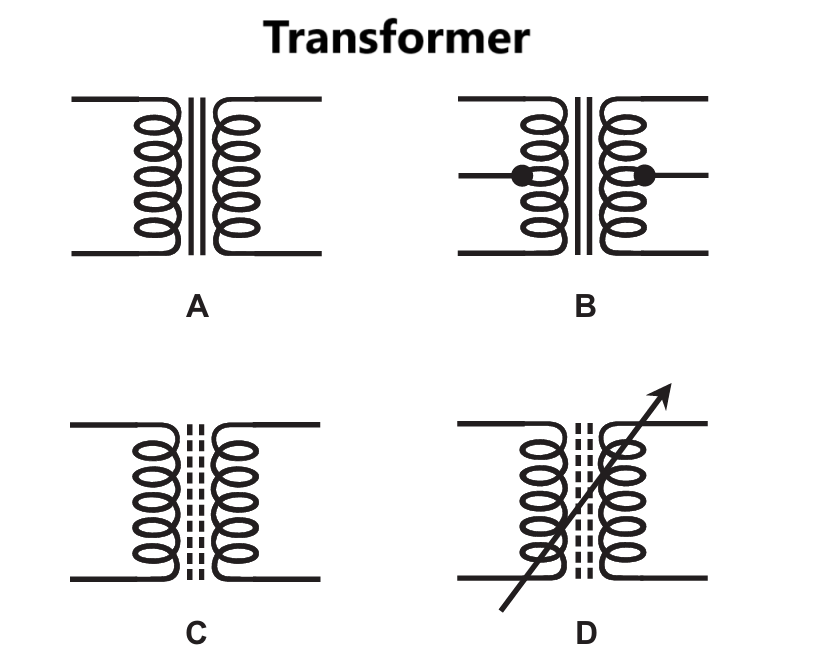
- Transformer: Transfers electrical energy between circuits via electromagnetic induction, consisting of primary and secondary windings around a core. Its symbol features two sets of coils (representing windings) around a central core, reflecting its structure and function.
Active Analog/Digital Components
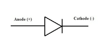
- Diodes: Diodes allow current to flow in only one direction (like a one-way valve), thanks to their PN junction. Their symbol features a triangle (representing the direction of current flow) and a vertical bar (representing the reverse bias barrier).
- Bipolar Junction Transistor (BJT): Acts as a switch or amplifier, with three terminals (collector, emitter, base) that control current flow. NPN and PNP transistors have distinct symbols, with arrow directions indicating current flow (leaving for NPN, entering for PNP).
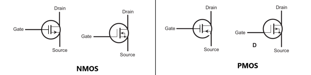
- MOSFET: A modified transistor with three terminals (drain, source, gate), using a metal-oxide insulator (like a capacitor) at the gate. Its symbol reflects this insulated gate structure, with a gap between the gate and the other terminals.
- SCR (Silicon Controlled Rectifier): A thyristor used to control high power, acting as a switch that turns on with a gate signal. Its symbol combines the diode shape with a gate terminal, reflecting its diode-like behavior with an enable pin.

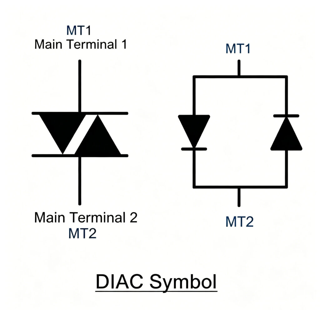
- DIAC (Diode for Alternating Current): A bidirectional trigger device that conducts current after exceeding its breakover voltage. Its symbol is symmetric, reflecting its bidirectional conduction capability.
Logic Gates
Logic gates are the fundamental building blocks of digital electronics, performing basic logical operations on binary inputs (0 and 1) to produce binary outputs. They are integral to digital circuits, including computers, microcontrollers, and other electronic devices. Common types of logic gates include:
- AND Gate: Outputs true (1) only if all inputs are true (1).
- OR Gate: Outputs true (1) if at least one input is true (1).
- NOT Gate: Inverts the input, outputting true (1) if the input is false (0) and vice versa.
- NAND Gate: Outputs false (0) only if all inputs are true (1); otherwise, it outputs true (1).
- NOR Gate: Outputs true (1) only if all inputs are false (0).
XOR Gate: Outputs true (1) if an odd number of inputs are true (1).
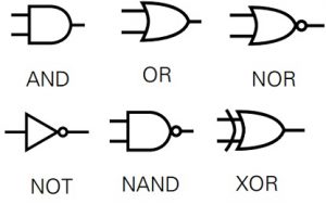
These gates are combined in various ways to perform complex logical operations, forming the backbone of digital computing.
Conclusion
Circuit symbols are an indispensable tool for understanding, designing, and troubleshooting electrical and electronic circuits. Standardized symbols ensure accurate communication between professionals, reduce errors, and streamline the entire design and production process. By understanding the physics behind each symbol, engineers and technicians can better grasp component functions and optimize circuit performance.
Whether you are a student learning the basics of electronics, a hobbyist building simple circuits, or a professional engineer designing complex PCBs, mastering circuit symbols is key to success. Learning to create custom symbols further expands your design capabilities, allowing you to work with specialized or new components and bring your projects to life.
About US
Founded in 2012, JKRGLO strives to build a one-stop platform for the electronic industry chain. By integrating PCB manufacturing, component procurement and PCB assembly services, we enable digital PCBA processing. With increasing investment in innovation and digital systems, we have achieved rapid growth and emerged as a leading PCB and PCBA manufacturer in the industry, capable of rapidly producing high-reliability and cost-effective products.