IPC-A-610 Standard: Practical Guide to PCBA Acceptance Criteria
서론
간단한 답변:IPC-A-610 is the global industry standard for visual quality acceptance of printed circuit board assemblies (PCBA). Published and maintained by IPC, it defines uniform, measurable criteria for component placement, solder joint integrity, cleanliness, and traceability across three reliability classes. The latest Revision J (2024) updates conformal coating rules and adds guidance for modern SMD packages. It is the universal baseline for QC in professional PCB assembly operations.
Introduction
If you’ve ever gone back and forth with a customer or QC inspector over whether a solder joint passes or fails, you already know why IPC-A-610 matters.
It’s far more than a compliance checkbox. It’s the shared technical language that lets manufacturers, OEMs, and inspection teams agree on what “good quality” actually means — no subjective debates, no double standards. From prototype builds to full volume production, this standard keeps quality consistent across factories, regions, and suppliers.
This guide breaks down the core criteria you use day to day, explains the three product classes, and covers the key updates in the current revision.
What Is IPC-A-610?
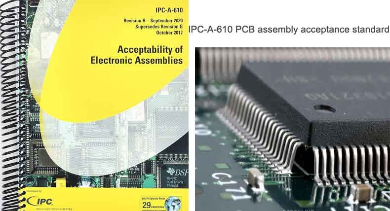
The current active version is Revision J, issued March 2024. It covers four core quality areas:
- Component placement, alignment, and orientation
- Solder joint formation and integrity
- Post-assembly cleanliness and conformal coating
- Marking, labeling, and product traceability
Core Acceptance Criteria
These are the four most referenced sections of the standard in day-to-day assembly work.
Component Placement
Rules cover alignment, side overhang, spacing, and polarity orientation for both through-hole and SMD components. The guiding principle: minor misalignment is acceptable, as long as minimum electrical clearance is maintained and the solder joint remains mechanically robust.
Solder Joint Quality
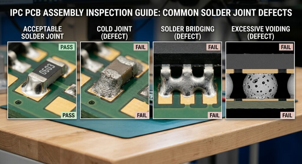
The most heavily used section. It defines acceptable fillet shape, wetting, voiding, and bridging limits for SMT, through-hole, and mixed-technology boards. A good joint is defined by smooth, concave fillets and complete wetting on both the PCB pad and component lead.
Cleanliness & Conformal Coating
Assemblies must be free of corrosive flux residue, loose debris, and conductive contaminants that could cause field failures. For conformal coated boards, the standard sets clear limits for bubbles, voids, and minimum coating thickness.
Marking & Traceability
All PCBAs and critical components must carry legible, permanent markings for identification and full traceability through production and service life.
IPC-A-610 Product Class Quick Reference
The standard applies different tolerances based on the product’s intended use case.
| Criteria | Class 1 (General) | Class 2 (Dedicated Service) | Class 3 (High Reliability) |
|---|---|---|---|
| Typical application | Consumer electronics | Industrial / business equipment | Medical, aerospace, military |
| Min. through-hole solder fill | Not specified | 50% | 75% |
| Component overhang rules | Most lenient | 보통 | Strictest |
| Inspection method | Sampled visual | Full visual | 100% visual + X-ray for critical ICs |
| Acceptable BGA void area | <25% per ball | <25% per ball | <15% for critical joints |
Key Updates in Revision J (2024)
- Expanded, clarified rules for conformal coating inspection (void size, bubble limits, coverage)
- Larger set of visual reference images for more consistent inspection across sites
- Updated guidance for bottom-terminated packages like QFN and LGA
- Refined criteria for no-clean flux residue acceptance
자주 묻는 질문 (FAQ)
A:What is the difference between IPC-A-610 and IPC-J-STD-001?
IPC-A-610 is the acceptance standard — it defines what a finished assembly should look like. IPC-J-STD-001 is the process standard — it defines how to solder and build the assembly. One is for inspection, the other for manufacturing.
A:How much void is allowed in a BGA solder ball?
Per the standard, a void is generally acceptable if it takes up less than 25% of the total solder ball area. Class 3 high-reliability products often apply tighter limits, typically 15%, especially for high-power or thermal joints.
A:Are no-clean flux residues acceptable under IPC-A-610?
Yes, provided they are non-corrosive, non-conductive, and do not obscure markings or interfere with inspection. For high-humidity or high-voltage environments, full cleaning is still recommended to prevent long-term electrochemical migration.
회사 소개
다음 내용도 참고해 보세요…

저자 소개
앤드류 잔 – JKRGLO.com 연구개발(R&D) 엔지니어
앤드류 잔(Andrew Zhan)은 PCB 업계에서 14년 이상의 연구개발(R&D) 엔지니어링 경력을 쌓아왔으며, 회로 설계 최적화 및 DFM 구현 분야에서 깊은 전문성을 보유하고 있습니다. 그는 복잡한 설계 요구 사항을 양산 가능한 솔루션으로 전환하는 데 주력하며, 시제품 제작과 양산 모두에서 기술 혁신을 주도하고 있습니다.
그는 여러 부서의 팀 및 고객과 긴밀히 협력하며, 프로젝트의 전체 수명 주기 동안 철저한 품질 검증과 원활한 기술적 소통을 보장합니다. 앤드류는 고객의 기대를 꾸준히 뛰어넘는, 신뢰할 수 있고 고성능의 PCB 솔루션을 제공하는 데 전념하고 있습니다.
목차
그래도 도움이 필요하신가요? 문의하기:
PCB 또는 PCBA 견적이 필요하신가요?
태그:
ipc 610
PCBA
ipc-610 certification
PCB
what is ipc 610