What is GND in a Circuit? Ground Types, Common Return Paths, and PCB Layout Rules
Introducción inicial
The Four Types of GND Symbols in Schematics
| Ground Type | Schematic Symbol | Physical Connection | Primary Application |
|---|---|---|---|
| Earth Ground (GND_E) | Triangle pointing down to a vertical line | Physical connection to the Earth via a grounded stake or mains pin | Heavy machinery, AC mains power supply safety, lightning protection |
| Chassis Ground (GND_C) | Diagonal lines (hatching) tied to a frame | Metal enclosure or mechanical casing of the product | ESD shielding, safety grounding, EMI containment |
| Analog Ground (AGND) | Triangle labeled 'A' or clean ground return | Isolated low-noise copper return path | Precision ADCs, operational amplifiers, sensor front-ends |
| Digital Ground (DGND) | Solid shaded triangle or 'D' label | High-speed switching return plane | Microcontrollers, FPGA logic, high-speed buses |
High-Frequency Return Current: The Rule of Minimum Inductance
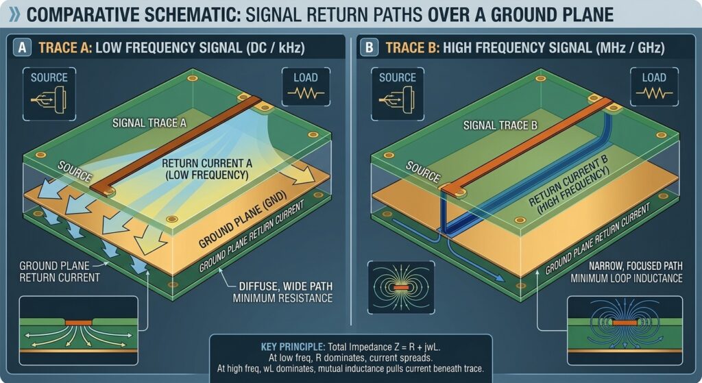
A common misconception among junior layout engineers is that return current takes the path of minimum resistance. While true for Direct Current (DC), alternating current (AC) and high-speed digital signals behave differently.
Return current always follows the path of minimum impedance (Z), where:
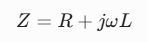
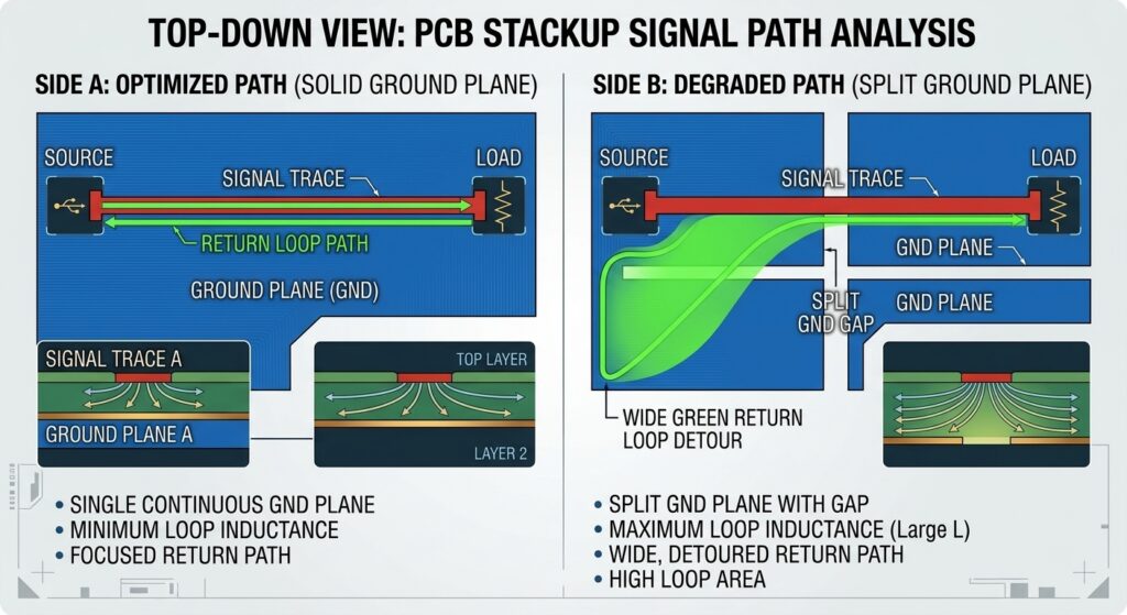
At frequencies above 100kHz, the inductive reactance term (jωL) dominates the resistive term (R). Consequently, return current pulls itself directly underneath the signal trace on the adjacent reference plane to minimize loop area (A) and loop inductance (L).

If a slot, split plane, or cutout intersects this return path, the return current must detour around the obstruction. This creates a large inductive loop area, causing:
Ground Bounce: Local voltage spikes across the ground plane.
EMI Radiation: The slot acts as an unintended slot antenna radiating electromagnetic noise.
Crosstalk: Overlapping return paths coupling noise into adjacent traces.
5 Essential PCB Grounding Rules of Thumb
To comply with IPC-2221 layout guidelines and pass EMC testing (such as FCC Part 15 or CE Class B), follow these layout constraints:
Maintain an Unbroken Solid Reference Plane: Avoid routing signal traces across split ground planes. If a trace must change layers, place a stitching via immediately adjacent to the signal via to allow the return current to transition smoothly between reference layers.
Single-Point Net Ties for AGND and DGND: Never tie Analog Ground and Digital Ground together randomly across the board. Connect them at a single point—typically at the Analog-to-Digital Converter (ADC) chip or via a zero-ohm resistor / ferrite bead—to prevent noisy digital switching currents from corrupting sensitive analog readings.
Keep ESD Return Paths Short: Connect TVS (Transient Voltage Suppressor) diodes and chassis ground mounts with wide, low-inductance traces directly to the main system ground to safely shunt electrostatic discharge away from core ICs.
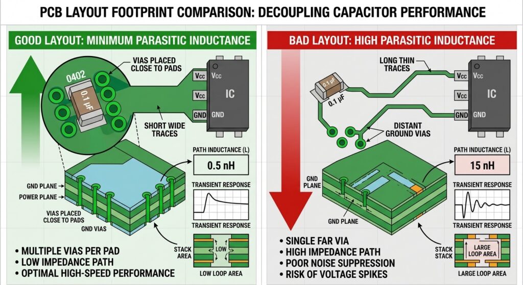
Decoupling Capacitor Placement: Place decoupling capacitors (e.g., $100\text{nF}$ MLCCs) as close as physically possible to the IC power pins. Connect the capacitor’s ground pad directly to the inner ground plane using a dedicated, short via to minimize parasitic loop inductance.
Implement Star Grounding for Power Supplies: In SMPS (Switch-Mode Power Supply) layouts, run high-current power return paths back to the output capacitor in a star topology rather than tying them into sensitive control signal grounds.
Ground Layout Reference Summary
| Design Challenge | Cause | Grounding Solution |
|---|---|---|
| Ground Bounce | High $di/dt$ switching through via/trace inductance | Use wide solid ground planes; place decoupling capacitors close to IC power pins |
| Radiated EMI / Failed EMC | Large return current loop area caused by plane slots | Eliminate splits beneath high-speed signals; add ground stitching vias near signal layer transitions |
| ADC Noise / Jitter | Digital ground noise coupling into analog ground | Use star grounding or a single-point net tie underneath the converter IC |
| ESD Damage | High-voltage transients entering signal paths | Route TVS diode ground pins directly to chassis/earth ground with short, wide traces |
Preguntas frecuentes (FAQ)
What is the difference between Neutral and Ground?
In AC power systems, Neutral is a current-carrying conductor that completes the circuit back to the power source under normal operation. Ground (Earth Ground) is a safety conductor designed to carry current only during a fault condition (such as a short circuit to a metal enclosure) to trip circuit breakers and prevent electric shock.
Can a circuit function without an Earth Ground connection?
Yes. Battery-powered devices (such as smartphones or laptops) operate on a floating ground (local signal reference plane) without any physical connection to the Earth. Ground in these systems simply serves as the common zero-volt reference for onboard electronics.
Is a single continuous ground plane better than split AGND/DGND planes?
For most modern mixed-signal PCBs, a single, continuous ground plane is superior to physically split planes, provided components are grouped effectively into distinct analog and digital zones. Physical splits often create accidental return-path slots when traces cross the gap, causing severe EMI issues.
Quiénes somos

Acerca del autor
Andrew Zhan – Ingeniero de I+D en JKRGLO.com
Con más de 14 años de experiencia en ingeniería de I+D en el sector de las placas de circuito impreso (PCB), Andrew Zhan aporta una amplia experiencia en la optimización del diseño de circuitos y la implementación de prácticas de fabricación (DFM). Se centra en convertir requisitos de diseño complejos en soluciones listas para la producción, impulsando la innovación técnica tanto para la fabricación de prototipos como para la producción en serie.
En estrecha colaboración con equipos multidisciplinares y con los clientes, garantiza una rigurosa validación de la calidad y una comunicación técnica fluida a lo largo de todo el ciclo de vida del proyecto. Andrew se compromete a ofrecer soluciones de placas de circuito impreso (PCB) fiables y de alto rendimiento que superen constantemente las expectativas de los clientes.
Índice
¿Aún necesitas ayuda? Ponte en contacto con nosotros:
¿Necesitas un presupuesto para una placa de circuito impreso (PCB) o un conjunto de placa de circuito impreso (PCBA)?
Etiqueta:
pcb order
gnd definition