
SMD Capacitor Identification Guide: Codes, Markings, and Practical Tips
Identifying SMD (Surface Mount Device) capacitor codes is one of the most common challenges for electronics engineers, repair technicians, and hobbyists alike. Unlike resistors or diodes, which follow standardized labeling systems, SMD capacitors have markings that vary drastically by type—and in most cases, they have no markings at all.
As essential components for storing electrical charge, SMD capacitors play a vital role in nearly every electronic device: they filter power supply noise, stabilize voltage, set oscillator timing, and couple signals between integrated circuits (ICs). Correctly identifying their values, voltage ratings, and polarity is not just a technical skill—it’s critical for ensuring circuit safety, functionality, and long-term reliability.
This guide breaks down the process of identifying any SMD capacitor on your PCB (Printed Circuit Board) with step-by-step instructions, practical examples, and solutions to common pitfalls.
What is an SMD Capacitor Code and Why Does It Matter?
An “SMD capacitor code” is not a single, universal standard—it’s a collection of marking systems tailored to the capacitor’s type, size, and manufacturer. These codes can appear as 3-digit numbers, single letters, polarity indicators, or even no marking at all (the most common scenario for MLCCs).
Understanding these codes is essential for every stage of electronics work, from design and assembly to debugging and repair:
- Safety First: Polarized capacitors (like tantalum and aluminum electrolytic types) require correct orientation. Reversing a polarized capacitor can cause it to overheat, short-circuit, or even explode, leading to catastrophic PCB damage and safety hazards.
- Circuit Functionality: The capacitance value (e.g., 104 = 0.1µF) ensures the correct component is used in the right place. A simple mistake—like using a 10µF capacitor instead of a 1µF one for timing—can cause the entire circuit to fail or behave unpredictably.
- Design Integrity: For unmarked MLCCs, the absence of a code is itself a clue: critical parameters like voltage rating and dielectric type (C0G vs. X7R) are only found in the Bill of Materials (BOM). This reinforces the importance of thorough documentation and prevents costly assumptions.
Step 1: Visually Distinguish the Three Core SMD Capacitor Types
Before you can read an SMD capacitor’s code, you must first identify its physical type. The marking system you use depends entirely on whether you’re dealing with an MLCC, tantalum capacitor, or aluminum electrolytic capacitor.
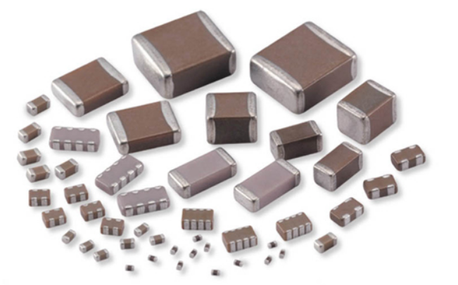
1. Multilayer Ceramic Capacitors (MLCCs)
The most common SMD capacitors—accounting for over 90% of all SMD capacitors in modern electronics—are non-polarized and typically unmarked.
- Appearance: Tiny, rectangular chips, usually in shades of beige, gray, or light brown. They have no physical polarity indicators and come in standard package sizes (Imperial: 0402, 0603, 0805, 1206; Metric: 1005, 1608, 2012, 3216) based on their dimensions.
- Key Uses: The “workhorse” of electronics, used for high-frequency decoupling (bypassing), power supply filtering, and timing/RF circuits. Their small size and low cost make them ideal for compact devices like smartphones and wearables.
- Marking: Almost always unmarked—this is their defining characteristic, which we’ll address in Step 2.
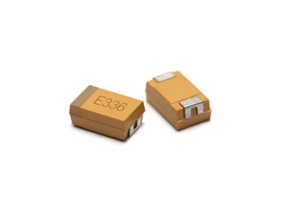
2. Tantalum Capacitors (SMD Chip Tantalum)
Molded, polarized capacitors with clear markings for value, voltage, and polarity. They use tantalum oxide as the dielectric material, offering high volumetric efficiency (large capacitance in a small space).
- Appearance: Well-molded rectangular or oval packages, often in black, tan, or yellow. They have a distinct, solid shape compared to the thin, flat MLCCs.
- Key Uses: Ideal for applications where space is limited but high capacitance is needed, such as power supply filtering in mobile devices, laptops, and industrial controls. They have low Equivalent Series Resistance (ESR) but are sensitive to overvoltage and reverse polarity.
- Marking: Always marked with capacitance, voltage rating, and a clear polarity indicator—critical for safe installation.
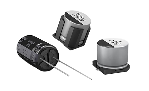
3. Aluminum Electrolytic Capacitors (SMD V-Chips)
Polarized capacitors with a cylindrical metal “can” mounted on a square plastic base. They use aluminum oxide and electrolyte as the dielectric, offering the highest capacitance values among SMD capacitors.
- Appearance: Cylindrical metal body (often silver or black) on a black plastic base. Some have a stripe or shaded area on the base to indicate polarity.
- Key Uses: Bulk energy storage and low-frequency filtering, typically used on the input or output of power supplies. They are available in both traditional electrolytic and solid electrolyte variants (more durable, longer lifespan).
- Marking: Always marked with capacitance, voltage rating, and a polarity indicator—never install one without checking this.
Step 2: The "Unmarked" Mystery – Identifying Multilayer Ceramic Capacitors (MLCCs)
The most important lesson for SMD capacitor identification: Over 90% of the capacitors on your PCB are MLCCs, and they are unmarked for a simple manufacturing reason.
MLCCs are made by layering ceramic dielectric material and metal electrodes, then firing the assembly at temperatures over 1000°C to sinter the ceramic. This intense heat would destroy any markings applied before firing, and adding markings after firing is an expensive, time-consuming step that’s impractical for mass-produced components (billions are made annually).
So, how do you identify an unmarked MLCC? The short answer: You can’t—at least not visually. The only reliable source of information is your Bill of Materials (BOM).
This is why documentation is critical. A 104 (0.1µF) MLCC specified as a 50V C0G dielectric is physically identical to a 104 (0.1µF) MLCC specified as a 10V X7R. One is a high-stability component for precision filters; the other is a general-purpose decoupling cap. Only your BOM and assembly partner know the difference.
Unmarked MLCC Specifications: Dielectric Codes (C0G vs. X7R vs. Y5V)
The most important parameter for an MLCC—found only in the BOM—is its dielectric type, which determines stability, capacitance range, and application suitability. MLCC dielectrics are divided into three main classes based on their temperature stability:
| Dielectric | Class | Key Characteristics | Typical Applications |
|---|---|---|---|
| C0G (NP0) | Class 1 | Ultra-stable; capacitance does not change with temperature, voltage, or time. Tolerance is typically ±5% or better. | RF circuits, oscillators, precision filters, and high-frequency applications. |
| X7R | Class 2 | Stable for general use; capacitance can change ±15% with temperature and voltage. Offers a good balance of performance and cost. | Power supply decoupling, general-purpose filtering, and most non-critical applications. |
| Y5V | Class 3 | General-purpose; high capacitance in a small size, but poor stability (capacitance can drop up to 80% over its temperature range). | Non-critical bulk decoupling, low-frequency circuits where stability is not a priority. |
Step 3: Decoding Marked SMD Capacitors (Tantalum & Aluminum Electrolytic)
Tantalum and aluminum electrolytic (V-Chip) capacitors are always marked, making them easier to identify than MLCCs. Their codes follow consistent systems for capacitance, voltage, and tolerance—here’s how to decode them.
A. Capacitance Value: 3-Digit Code & Spelled-Out Units
Capacitance is the most critical value, and it’s marked in two ways:
- Spelled-Out Units: Larger V-Chips often have the capacitance and voltage printed directly (e.g., 220µF 25V). Watch for legacy abbreviations:
- MFD: A common abbreviation for µF (microFarad) on older parts and schematics.
- MF: Also used to mean µF (microFarad)—milliFarad (mF) is rarely used in standard electronics design.
- 3-Digit Code: The most common system for smaller marked capacitors (tantalum and small V-Chips). The base unit is always Picofarads (pF),Format is XXY = XX × 10 pF.
- 105 = 10 × 10 pF = 1,000,000 pF = 1,000 nF = 1µF
- 226 = 22 × 10 pF = 22,000,000 pF = 22,000 nF = 22µF
- 477 = 47 × 10 pF = 470,000,000 pF = 470,000 nF = 470µF
B. Voltage Rating: EIA Letter Code
A single letter is used to indicate the maximum DC voltage rating of the capacitor. Below are the most common EIA voltage codes for SMD tantalum and aluminum electrolytic capacitors:
| Letter | Voltage (V) | Letter | Voltage (V) |
|---|---|---|---|
| f | 4V | E | 25V |
| j | 6.3V | V | 35V |
| A | 10V | T | 50V |
| B | 12V | U | 63V |
| C | 16V | W | 100V |
Common Tantalum Capacitor Voltage Codes
Example: A tantalum capacitor marked “226A”
– Value: 226 → 22 × 10 pF = 22µF
– Voltage: A → 10V
– Result: 22µF, 10V Tantalum Capacitor
C. Tolerance: Letter Code
Some marked capacitors include a letter code to indicate the capacitance tolerance (how much the actual value can vary from the marked value). Common tolerance codes are:
| Code | Tolerance |
|---|---|
| J | ±5% |
| K | ±10% |
| M | ±20% |
| Z | +80%, -20% (Common for Y5V MLCCs and low-cost electrolytics) |
Common Capacitor Tolerance Codes
Step 4: Polarity – The Non-Negotiable Marking for Safe Use
Polarity is the most critical marking on SMD capacitors—ignoring it can lead to component failure, PCB damage, or even fire. Tantalum and aluminum electrolytic capacitors are polarized, and their polarity markings follow distinct rules (a common source of confusion for beginners).
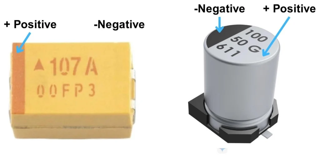
Comparing SMD capacitor polarity: Tantalum capacitor with a positive bar, and a V-Chip with a negative stripe.
Tantalum Capacitor Polarity Markings
- A solid bar, stripe, or bevel on the package indicates the POSITIVE (Anode) side.
- Critical Warning: This is the opposite of through-hole electrolytic capacitors, where the stripe indicates the negative side. This is a common mistake that leads to component failure—always double-check the part type!
- Note: Tantalum capacitors should be used at 50% of their rated voltage (derating) to avoid premature failure.
Aluminum Electrolytic (V-Chip) Polarity Markings
- A black shaded area on the plastic base, or a stripe on the metal can, indicates the NEGATIVE (Cathode) side.
- Some V-Chips also have a small “V” notch on the positive side, but the shaded area is the most reliable indicator.
Troubleshooting: Fixing Common SMD Capacitor Identification Issues
Even with these rules, you’ll encounter tricky situations. Below are solutions to the most common SMD capacitor identification problems.
Challenge 1: In-Circuit Measurement of Unmarked MLCCs
- Problem: You try to measure an unmarked 0.1µF (104) MLCC with a multimeter, but the reading shows 3.2µF instead.
- Solution: You’re measuring the entire power rail, not just the target capacitor. The multimeter detects the target cap in parallel with other decoupling caps, IC internal capacitance, and other components. The only reliable way to measure an MLCC is to desolder at least one side to isolate it from the circuit.
Challenge 2: Polarity Confusion Between Tantalum and Aluminum Electrolytic Capacitors
- Problem: A technician replaces a failed tantalum capacitor with the correct value and voltage but orients it with the stripe to the negative side. The board powers on, and the new capacitor immediately fails.
- Solution: Memorize this rule: Stripe on Tantalum = Positive; Stripe on Aluminum Electrolytic = Negative. Always confirm the part type before installation—never assume based on stripe alone.
Challenge 3: Mistaking MLCC Package Size for Value
- Problem: You assume a 1206 MLCC has a higher capacitance than a 0603 MLCC of the same type.
- Solution: MLCC package size (0402, 0603, etc.) refers to physical dimensions, not capacitance. A 0603 MLCC can have the same capacitance as a 1206 MLCC—package size depends on voltage rating and current handling, not value. Always check the BOM for capacitance details.
Challenge 4: Misinterpreting Legacy "MF" or "MFD" Markings
- Problem: An old repair schematic calls for a “22MF” capacitor, and you can’t find a milliFarad capacitor of that size.
- Solution: “MF” and “MFD” are legacy abbreviations for µF (microFarad), not milliFarad. A “22MF” capacitor is almost always 22µF—milliFarad capacitors are extremely rare in standard electronics.
Conclusion
Identifying SMD capacitors boils down to two key rules: For the 90% of unmarked MLCCs, trust your BOM—there’s no way to visually determine their parameters. For the 10% of marked capacitors (tantalum and aluminum electrolytic), decode the 3-digit value code, voltage letter code, and polarity marking carefully.
Never underestimate the importance of documentation: A tiny, unmarked MLCC isn’t just a “104”—it could be a 50V C0G for a precision filter or a 10V X7R for simple decoupling. The package won’t tell you the difference, but your BOM will.
Mistakes in SMD capacitor identification can lead to costly repairs, circuit failure, or safety hazards. By following the step-by-step guide above, you’ll be able to identify any SMD capacitor with confidence—whether you’re designing a new PCB, debugging a faulty device, or repairing electronics.
our PCBA service prioritizes BOM integrity. We verify every component against our extensive library, ensuring the exact dielectric, voltage, and tolerance you specify are placed with machine precision. Upload your Gerbers and BOM today to get an instant PCBA quote.
About US
Founded in 2012, JKRGLO strives to build a one-stop platform for the electronic industry chain. By integrating PCB manufacturing, component procurement and PCB assembly services, we enable digital PCBA processing. With increasing investment in innovation and digital systems, we have achieved rapid growth and emerged as a leading PCB and PCBA manufacturer in the industry, capable of rapidly producing high-reliability and cost-effective products.