
FR4 PCB
HOME / PCB Fabrication
What is an FR4 PCB?
Flame Retardant 4, or FR4, is a material grade used in PCB manufacturing. It is made of fibreglass and “4” represents the UL94 V-0 flammability standard (it must self-extinguish after being ignited). Fibreglass reinforced woven glass fibre and epoxy resin with makes it excellent for electrically insulated applications. FR4 is a widely used material due to its low cost and high reliability.
FR4 Material Overview
FR4 represents flame-retardant grade 4 glass-reinforced epoxy laminate. The material’s dielectric constant and dissipation factor (loss tangent) are moderate. FR4 can be used in low-speed and high-power applications, making it the first choice for many hobbyists. This makes it suitable for general-purpose electronic designs. Dielectric constant: around 4.5 at 1MHz (moderate). Loss tangent: around 0.02 at 1MHz (moderate). The glass transition temperature (Tg) determines how the material behaves under heat. It is one of the most important thermal properties in the classification of FR4 materials.
Low Tg (130–140°C)
Standard Tg (150–160°C)
High Tg (>170°C)
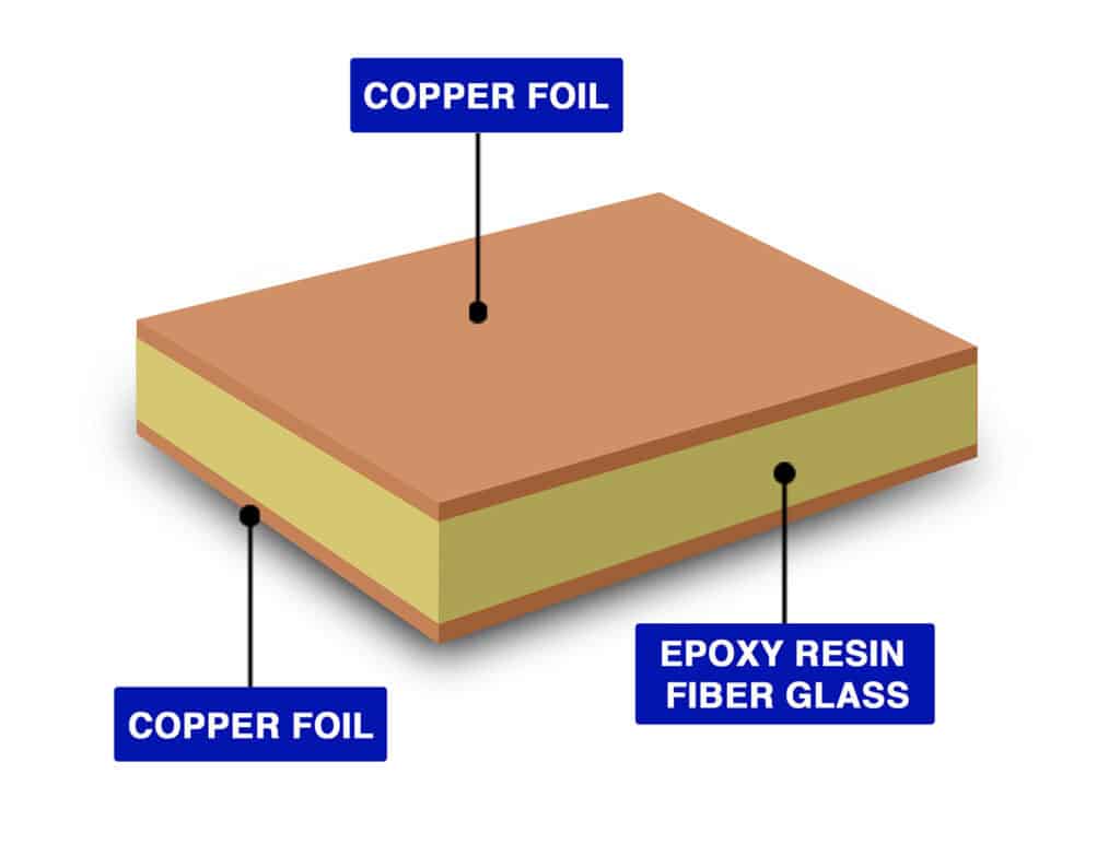
Structure and Properties of FR4
FR-4 is a composite material used as the substrate in PCBs. Its structure is made from:
Benefits of FR4 PCB Material
Cost-Effective and Widely Available
FR-4 is affordable compared to advanced laminates like Rogers. Its low cost makes it popular and the industry standard for most applications. It is globally available, making it easy to source for large production volumes.
Good Mechanical Strength
The woven fiberglass provides higher tensile strength, making it more resistant to warping, bending, and mechanical stress.
Reliable Electrical Insulation
Due to a moderate dielectric constant, it is excellent for low-frequency and higher-power applications. Additionally, the epoxy-fiberglass structure offers higher signal isolation.
Benefits of FR4 PCB Material
1. Signal Integrity and Impedance Control
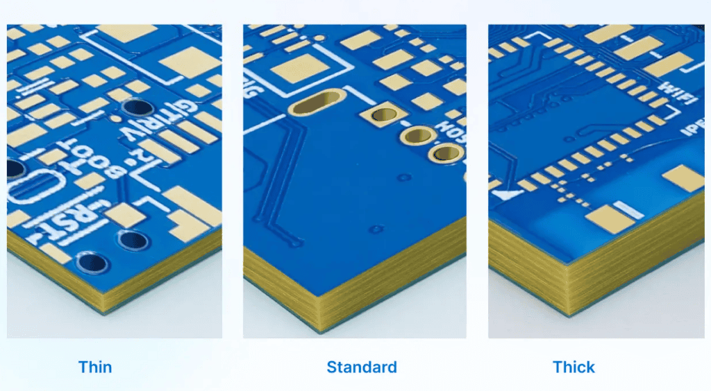
Thicker FR-4 increases the dielectric spacing, which raises impedance by introducing parasitic components. FR-4 thickness can be adjusted to control impedance for different circuit applications.
Thinner FR-4 has a smaller dielectric spacing between copper layers, which lowers the impedance of traces. However, the higher dielectric loss of FR-4 limits performance above a few GHz regardless of thickness.
2. Thermal Management
Thicker FR-4 offers improved heat spreading and higher thermal capacity, which helps reduce the risk of localized overheating.
Thinner FR-4 has limited heat-spreading capability on high-power boards, making it more susceptible to hot spots.
3. Mechanical Stability
Thicker boards are more rigid and resistant to bending, which makes FR4 more suitable for mechanically stressed assemblies.
Thinner boards are more flexible and lightweight, making them ideal for compact devices but more prone to warping.
Common Applications of FR4 PCBs
1. Consumer Electronics
FR4 PCBs balance cost and strength for everyday electronic devices. From smartphones to wearables, FR-4 provides durable and reliable PCB solutions.
2. Industrial Control Systems
Control systems, power supplies, and automation boards often use thicker FR-4 laminates. FR4 PCB for mechanical rigidity and ability to withstand moderate thermal cycling.
3. Automotive Electronics
Instrument clusters, infotainment units, and sensor modules frequently use FR-4 PCBs. FR4 PCBs provide stable performance under vibration and moderate heat.
JKRGLO FR4 PCB Manufacturing Capabilities
FR4 PCB Manufacturing Capabilities
| Features | Capabilities |
| Layer count | 1, 2, 4, 6, ...32 layers |
| Controlled Impedance | 4/6/8/10/12/14/16/18/20/.../32 layers |
| Impedance Tolerance | ±10% (±5Ω if value ≤ 50Ω) |
| Maximum Dimensions | 670 × 600mm (Thickness ≥ 0.8mm); |
| 500 × 600mm (Thickness < 0.8mm); | |
| 2-layer reaches 1020 × 600mm. | |
| Minimum Dimensions | 3 × 3mm; 70 × 70 for V-cut panel |
| Outer Copper Thickness | 1oz, 2oz (2.5oz, 3.5oz, 4.5oz for 2-layer) |
| Inner Copper Thickness | 0.5 oz, 1 oz, 2 oz |
| Surface finish | HASL (leaded / lead-free), ENIG(1u" / 2u") |
| Minimum Via Hole/Diameter | 0.15mm / 0.25mm |
| Hole Size Tolerance | ① Plated: Through-holes: +0.13 / -0.08mm ; Press-fit holes:±0.05mm |
| ② Non-plated: ±0.2mm | |
| Minimum Plated Slots | 0.5mm |
| Minimum Non-Plated Slots | 1.0mm |
| Plated Edges | Available with PCB size 10 × 10mm, thickness: 0.6mm. ENIG is required. |
| Blind Slot | Available in 2-32 layer boards with a thickness of ≥ 0.8mm. |
| Countersink Hole | Available in 2-32 layer boards with a thickness of ≥ 0.6mm. Supported countersink angle: 90°/135° |
| Backdrill | Available in 4-32 layer boards with a thickness of ≥ 0.8mm. Holes will be epoxy resin filled after backdrilling. |
| Castellated Holes | Available with PCB size 10 × 10mm. |
| Minimum Track Width and Spacing | ① 1oz: 0.10 / 0.10mm (4 / 4mil) for 1/2-layer ; 0.09 / 0.09mm (3.5 / 3.5mil) for muliti-layer |
| ② 2oz: 0.16 / 0.16mm (6.5 / 6.5mil) for 1/2-layer; 0.16 / 0.20mm (6.5 / 8mil) for multi-layer | |
| Minimum BGA Pad Diameter | 0.25mm |
| Gold Fingers Bevelling | 30° or 45° |
Why Choose JKRGLO FR4 PCBs?
Cost-Effective Production
FR4 PCBs from just $1. Equipped with professional production facilities, we manufacture up to 200,000 pieces per day.
Extensive Capability
Supports 1–32 layers, board thickness from 0.2mm to 3.2mm, and copper weights up to 3oz.
High Customization
Pick from 7 solder mask colors, multiple finishes, and copper thickness options to fit any project.
Fast & Global Delivery
Prototypes in as fast as 24 hours, shipped to over 200 countries worldwide.
Submit a FR4 PCB Quote Now
Frequently Asked Questions About FR4 PCB
What is the dielectric constant (Dk) of FR4 material?
FR4 typically has a dielectric constant of around 4.2–4.8 at 1 MHz. This property affects signal transmission speed and impedance control, making it an important factor in high-speed and RF designs.
What is the glass transition temperature (Tg) of FR4?
Standard FR4 has a Tg of about 130–140 °C, while high-Tg FR4 options can reach 170–180 °C or higher. Choosing the right Tg ensures PCB stability under high operating temperatures.
Is FR4 suitable for high-frequency circuits?
FR4 works well for most low- and mid-frequency applications. However, for RF or microwave circuits above ~1 GHz, specialized materials like Rogers or PTFE are recommended due to lower dielectric loss.
How does FR4 perform in multilayer PCB designs?
FR4 is widely used for multilayer PCBs (up to 40+ layers). Its insulating properties, mechanical strength, and cost-effectiveness make it a reliable choice for complex stack-ups.
Are FR4 PCBs RoHS compliant and environmentally safe?
Yes. Most modern FR4 laminates areRoHS- and REACH-compliant; halogen-free options are also available, supporting eco-friendly and sustainable electronics manufacturing.
How does PCB material FR4 compare with other PCB substrates?
Compared to high-frequency PCB materials like Rogers or PTFE, FR4 has higher dielectric loss but is far more cost-effective. For most standard applications, FR4 is the go-to option, while specialized materials are chosen for RF or microwave circuits.
Flexible PCB
HOME / PCB Fabrication
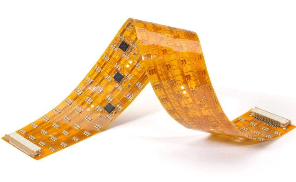
What is a Flexible PCB?
A Flexible PCB (also called flex PCB or FPC) is a type of printed circuit board that can bend, fold, and twist without breaking. Unlike rigid boards, flexible PCBs are designed to adapt to tight spaces and dynamic environments, making them ideal for compact and lightweight electronic devices.
How Flexible PCBs Differ from Rigid PCBs
Rigid PCBs are built on FR4 substrates, which makes them stiff and less adaptable to tight spaces. Flexible PCBs, in contrast, use polyimide substrates that allow the board to bend and twist without damage. Conductive copper layers carry signals across the base material, while protective coverlays or conformal coatings ensure durability. Thanks to this flexibility, FPCs save space, withstand vibration better, and enable 3D packaging solutions that rigid boards simply cannot achieve.
Structure and Properties of FR4
The structure of a Flexible PCB is built on thin, bendable substrates such as polyimide (PI) or PET, which provide excellent mechanical flexibility and heat resistance. Copper foil is laminated onto the substrate to form the conductive traces, while coverlays or solder masks protect the circuits. Depending on the application, stiffeners can be added in certain areas to strengthen connectors or mounting points without affecting the overall flexibility.
Flexible PCBs combine mechanical adaptability with electrical reliability. They can be bent, folded, or twisted to fit into compact or irregularly shaped devices, all while maintaining stable electrical performance.
Key properties include:
High Flexibility – withstands repeated bending without damage.
Lightweight and Thin – saves space and reduces overall device weight.
Durability – resistant to vibration, thermal stress, and dynamic movement.
Design Versatility – supports complex layouts with fewer connectors and cables.
Advantages of Flexible PCBs
Space and Weight Savings
Flexible PCBs are very thin and lightweight. They reduce the need for bulky wires in a system where space is a constraint. And because of this flexibility, we can design compact devices.
Durability and Flexibility in Harsh Environments
Flexible PCBs come with superior bend endurance. They enhance the overall bending ratio and bending frequency. Due to their good thermal stability, FPCs perform well in applications exposed to mechanical stress and vibrations.
Improved Signal Integrity
Thickness is reduced, which means less spacing between layers and shorter ground return paths. This will reduce the overall crosstalk and improve signal integrity in high-speed designs.
Benefits of FR4 PCB Material
1. Bend Radius and Layer Count
The minimum bend radius defines how tightly a flexible PCB can be bent without causing cracks or delamination. This parameter depends on both the layer count and material type. In general, more layers reduce flexibility, so designs requiring frequent bending should minimize layer count.
2. Material Selection
Polyimide (PI) is the most commonly used material thanks to its excellent thermal resistance and mechanical durability. Its ability to withstand high temperatures makes soldering components reliable and secure.
Polyester (PET) is a cost-effective alternative, suitable for low-cost or disposable devices. However, it has limited heat resistance and is not ideal for applications requiring repeated soldering.
3. Trace Routing and Pad Design
To ensure mechanical reliability, designers often use curved traces, staggered vias, and teardrop pads. These techniques help reduce stress concentration points, preventing cracks and enhancing long-term durability.
Common Applications of FR4 PCBs
1. Consumer Electronics
Flexible PCBs are widely used in smartphones, wearables, and laptops to save space and enable ultra-slim designs. By allowing components to connect within tighter spaces, FPCs make compact and lightweight devices possible.
2. Medical Devices
In medical technology, weight and reliability are critical. FPCs are commonly used in pacemakers, hearing aids, and diagnostic equipment. Their ability to bend and flex allows them to withstand natural body movements without compromising performance.
3. Automotive Electronics
From electric vehicles to in-car audio systems, FPCs play a vital role. Unlike rigid boards that are prone to vibration damage, flexible PCBs can endure both heat and mechanical stress, making them ideal for sensors and control systems.
4. Aerospace and Aviation
In aerospace and aviation, reducing weight is critical. FPCs are used in satellites, avionics, and other flight systems because their lightweight design helps lower launch costs and improve fuel efficiency without sacrificing reliability.
JKRGLO Flexible PCB Manufacturing Capabilities
Flexible PCB Manufacturing Capabilities
| Features | Capabilities |
| Minimum Dimensions | No limit. Panel suggested if dimension < 20×20mm. |
| Maximum Dimensions | Regular: 234 × 490mm |
| Absolute limit: 250 × 600mm with edge rails | |
| Dimension Tolerance | ±0.1mm/±0.05mm(extra charged) |
| Coverlay Color | Yellow / Black / White/ Transparant |
| Surface Finish | ENIG. Thickness: 1u" / 2u" |
| Min. Via hole size/diameter | ①Regular: 0.15mm/0.35mm |
| ②Extreme: 0.10mm/0.3mm (extra charged) | |
| Minimum Plated Slot | 0.50 mm |
| Minimum Non-Plated Slot | No limit |
| Annular Ring for PTH | ≥ 0.25 mm. Absolute limit: 0.18mm |
| Minimum Trace Width/Spacing | ① 12μm (1/3oz) copper: 3/3mil (absolute limit 2/2mil) |
| ② 18μm (0.5oz) copper: 3.5/3.5mil | |
| ③ 35μm (1oz) copper: 4/4mil | |
| Stiffener Material | PI(0.1mm, 0.15mm, 0.20mm, 0.225mm, 0.25mm) |
| FR4(0.1mm, 0.2mm, 0.4mm, 0.6mm, 0.8mm, 1.0mm, 1.2mm, 1.6mm) | |
| Stainless Steel(0.1mm, 0.2mm, 0.3mm) | |
| 3M Tape(tesa8854, 3M9077, 3M468) |
Why is JKRGLO the Go-To Flexible PCB Manufacturer?
Flexible Material Choices
From ultra-thin 25μm substrates to tear-resistant 50μm, transparent PET (85% transmittance), and advanced 4-layer stackups, JKRGLO covers every design need.
Precision You Can Trust
With LDI exposure and dry film, JKRGLO delivers 2/2mil traces without pad deviation. Laser cutting enables virtually any shape with ±0.05mm tolerance.
Reliable Quality & Durability
Using adhesive-free substrates and offering multiple stiffener options, JKRGLO ensures excellent bending performance and long-lasting stability.
Cost-Effective & Fast
Affordable factory-direct pricing combined with dependable 4-5 day lead times, giving you the best balance of cost, speed, and reliability.
Submit a Flexible PCB Quote Now
Frequently Asked Questions About Flexible PCB
What materials are used in flexible PCBs?
Polyimide and polyester films are the most common substrates for flexible PCBs. They can be chosen on the basis of cost and thermal stability.
How many times can a flexible PCB bend?
A well-designed flex PCB can withstand thousands to millions of flex cycles, depending on material and bend radius.
What is the minimum bend radius for a flexible PCB?
Typically, the bend radius will be around 10 times the thickness of the board for dynamic flexing and 6 times for static bends, though actual values depend on copper type, layer count, and material selection.
Are flexible PCBs more expensive than rigid PCBs?
Yes, flexible PCBs are generally more expensive per unit than rigid boards due to materials and processing. However, they often lower the total system cost by reducing connectors, cables, assembly steps, and space requirements, and can be chosen for RF or microwave circuits.
When to use a flexible PCB?
Flexible PCBs are ideal when space savings, lightweight construction, or repeated bending are required. They are commonly used in compact devices, dynamic applications (like foldable electronics or hinges), and in systems where connectors and cables can be replaced to improve reliability and reduce assembly steps.
What are the disadvantages of Flex PCB?
Flex PCBs are more costly to manufacture than rigid boards due to specialized materials and processes. They also require careful design to manage bend radius and stress points. Additionally, handling and assembly need more attention to avoid damage, as flexible circuits are thinner and more delicate than rigid ones.
How many layers does a flex PCB have?
A flex PCB can range from a simple single-layer design to complex multilayer structures, depending on the application. Typical builds include 1-4 layers, but advanced designs can reach 6-8 layers or more when combined with rigid-flex technology.
High Frequency PCB
HOME / PCB Fabrication
What is a High Frequency PCB?
As the frequency increases beyond a certain limit, signal losses in standard FR4 boards rise significantly. To address this, we offer a range of High-Frequency PCBs, designed specifically for MHz to GHz applications. These boards use low-loss dielectric materials with a reduced loss tangent, minimizing signal degradation. This ensures controlled electromagnetic interference (EMI) and reliable, high-speed signal transmission.
Common Materials for High Frequency PCB
Unlike standard FR4 boards, High-Frequency PCBs can be selected based on Dk (dielectric constant) and Df (dissipation factor). The lower these values, the better the signal integrity at high frequencies. Some materials JLCPCB offers include:
Rogers Material:
RO4350B (Dk=3.48, Df=0.0037)
Rogers-RO4350B:
This material is a strengthened glass hydrocarbon/ceramic material with a dielectric constant of 3.48 at 10GHz, which makes it commonly used in high-frequency power amplifier designs. The RO4350B laminate has a low Z-axis coefficient of thermal expansion (CTE), which ensures high stability of multilayer circuits interconnected by plated through holes (PTH).
PTFE Teflon Material:
ZYF255DA (Dk=2.55, Df=0.0018)
ZYF265D (Dk=2.65, Df=0.0019)
ZYF300CA-C (Dk=2.94, Df=0.0016)
ZYF300CA-P (Dk=3.0, Df=0.0018)
Rogers-RO4350B:
PTFE Teflon PCB has outstanding comprehensive performance in practical use and is an ideal material choice for high-complexity and high-reliability designs. It has good temperature resistance, strong heat dissipation, excellent dielectric properties, and good mechanical stability. It is very durable in use and can withstand a certain amount of oxidation and UV rays, so it is also a cost-effective option.
The Benefits of JKRGLO High Frequency PCB
Low Dielectric Loss
Lower loss in PCB dielectric means higher signal strength. Dielectric losses can cause EMI failure and excessive crosstalk. With a low dissipation factor (Df), signal losses can be controlled at high frequencies.
Stable Performance at High Speeds
At high speed, signals travel in dielectric space, and copper traces act as waveguides. Substrate having lower loss tangent (Df) ensures better signal performance throughout.
Excellent Signal Integrity
Factors like impedance mismatch and signal delays increase if the substrate has higher parasitic components. With high-frequency substrates, delays can be controlled in RF and high-speed circuits.
High Frequency PCB Design Considerations
1. Controlled Impedance
Trace width, spacing, and dielectric properties are used to tune the impedance. Impedance matching should be there for better signal transmission. That’s why in RF transmission lines 50Ω, 75Ω, and 100Ω are used.
2. Material Thermal Expansion Coefficient
Copper traces are placed on top of the substrate to form the electrical circuit. As the temperature changes, the substrate expands, and so does the copper. If there is a large mismatch, the traces can be damaged or broken.
3. Copper Foil Type and Plating
A good copper foil with a smooth surface and low resistance ensures lower losses at microwave frequencies. Plating choices such as ENIG or immersion silver must balance conductivity and reliability.
Common Applications of High Frequency PCBs
1. RF and Microwave Systems
RF and microwave systems operate in the 3 kHz to 300 GHz range, and high-frequency applications often require specialized materials. Materials like Rogers are therefore used to design RF front-end modules that demand high accuracy and minimal signal distortion.
2. 5G Infrastructure
Communication nowadays works with weak, small signals, and they need to be detected with a higher probability for reliability. These materials are used where ultra-low latency and high bandwidth are required.
3. Satellite Communication
Satellites are objects we send to space, and with a lot of investment, we do not want system failures due to external radiation and EMI. So these materials are used to handle long-range and high-frequency signals.
JKRGLO High Frequency PCB Manufacturing Capabilities
High Frequency PCB Manufacturing Capabilities
| Features | Capabilities |
|---|---|
| Minimum Drill | 0.2mm |
| Minimnum Track Width and Spacing | 0.10 / 0.10 mm (4 / 4 mil) |
| Minimum Dimensions | 3 × 3mm |
| Maximum Dimensions | 590*438mm |
| Layer | 2-layer |
| Thickness | 0.65mm,0.9mm,1.65mm |
| Copper Weight | 1oz |
| Soldermask Color | Green |
| Silkscreen | White |
| Surface finish | ENIG |
| Gold Thickness | 1U", 2U" |
Why Choose JKRGLO as Your High Frequency Manufacturer?
High-Frequency Performance
JKRGLO offers High Frequency PCBs using advanced materials like Rogers RO4350B and PTFE Teflon, delivering low-loss performance with a Dk of 2.55-3.48 and Df as low as 0.0016. These materials ensure exceptional signal integrity for high-speed applications from 1GHz to 40GHz.
Reliable Quality Assurance
JKRGLO’s industry-leading quality assurance process guarantees that each PCB undergoes rigorous testing, ensuring reliable and consistent performance at high frequencies. JKRGLO maintains high standards, so you can trust your designs to perform under demanding conditions.
Competitive Pricing
JKRGLO provides cost-effective solutions without compromising performance, making cutting-edge technology more accessible to your budget.
Fast Prototyping
With a 4-5 day prototyping turnaround, JKRGLO ensures fast delivery without sacrificing quality, so you can iterate and refine designs quickly.
Submit a High Frequency PCB Quote Now
Frequently Asked Questions About High Frequency PCB
What frequency range do high-frequency PCBs cover?
Typically, frequencies above 500MHz to a few GHz are used for RF, microwave, and 5G applications.
Why is Rogers material preferred over FR4 for high-frequency PCBs?
Rogers has lower dielectric loss and a more consistent dielectric constant. Dk and Df are relatively low, which is best for high-speed designs.
Can high-frequency PCBs be multi-layered?
Multi-layer stack-ups are common for complex RF and 5G designs requiring power/signal separation.
What are the challenges in manufacturing HF PCBs?
Precise impedance control, thermal management, and material handling are critical challenges compared to standard PCBs.
Metal Core PCB
HOME / PCB Fabrication
What is a Metal Core PCB?
A Metal Core PCB (MCPCB) is a printed circuit board that integrates a metal base, most commonly aluminum, but also copper or a copper alloy, designed to efficiently conduct and dissipate heat away from high-power electronic components. Unlike standard FR4 boards, MCPCBs feature a three-layer structure: a thermally conductive metal substrate, a thin dielectric layer with high thermal conductivity but electrical insulation, and a patterned copper circuit layer on top. This construction not only enhances thermal management and mechanical stability but also enables higher power densities and longer component lifetimes.
At JKRGLO, state-of-the-art lamination and precision drilling ensure excellent bonding between layers and minimal thermal resistance, resulting in MCPCBs that are reliable, durable, and tailored for demanding applications such as LED lighting, power converters, and automotive electronics.
Types of Metal Cores
The most common types of metal cores used in MCPCBs are aluminum and copper, each with distinct properties that suit different applications:
Aluminum Core PCB:
Aluminum is the most widely used metal core material due to its excellent balance of thermal conductivity, lightweight nature, and cost-effectiveness. It is ideal for LED lighting, consumer electronics, and automotive applications where heat dissipation is crucial but overall cost must remain low.
Copper Core PCB:
Copper offers superior thermal conductivity compared to aluminum, making it suitable for extremely high-power or high-frequency applications where maximum heat transfer is needed. Although heavier and more expensive than aluminum, copper cores are often preferred in power electronics, RF applications, and aerospace systems that demand top-tier thermal and electrical performance.
The Benefits of JKRGLO Metal Core PCB (MCPCB)
Superior Heat Dissipation
Metal core PCBs excel at drawing heat away from components thanks to their thermally conductive base. This helps maintain stable operating temperatures, prevents overheating, and prolongs the lifespan of sensitive electronics.
Higher Current Carrying Capacity
With better thermal conductivity, MCPCBs can safely handle higher current loads without performance drops. This makes them ideal for LED lighting, power converters, and other high-power electronics where reliable energy delivery is crucial.
Enhanced Mechanical Strength
The metal substrate provides increased durability and rigidity compared to standard FR4 boards. This added mechanical stability improves resistance to vibration and mechanical stress, essential for demanding industrial and automotive environments.
Metal Core PCB Design Considerations
1. Core Material Selection
Choosing between aluminum and copper cores affects thermal conductivity, weight, and cost.
2. Dielectric Layer Thickness
The thickness of the insulating layer impacts heat transfer efficiency and electrical performance.
3. Thermal Conductivity Ratings
Select the right thermal conductivity (measured in W/m·K) based on component heat loads and application requirements.
Common Applications of Metal Core PCBs
1. LED Lighting Systems
Efficient heat dissipation keeps LEDs cool, extending their lifespan and improving brightness stability.
2. Power Electronics
Used in power supplies, converters, and motor controllers, MCPCBs ensure reliable operation under high currents and elevated temperatures.
3. Automotive and Aerospace
Ideal for harsh environments, MCPCBs are used in automotive ECUs, aerospace control systems, and other heat-sensitive electronic assemblies.
JKRGLO Metal Core PCB Manufacturing Capabilities
Metal Core PCB Manufacturing Capabilities
| Features | Capabilities |
| Minimum Drill | 0.65mm(Aluminum Core) |
| 1.0mm(Copper Core) | |
| Minimnum Track Width and Spacing | 0.10 / 0.10 mm (4 / 4 mil) |
| Minimum Dimensions | 5 × 5mm |
| Maximum Dimensions | 602 × 506mm(Aluminum Core) |
| 480 × 286mm(Copper Core) | |
| Layer | 1-layer |
| Thickness | 0.8mm(Aluminum Only),1.0mm,1.2mm,1.6mm |
| Soldermask Color | White, Black |
| Surface finish | HASL(Aluminum Core), OSP(Copper Core) |
| Copper Weight | 1oz |
| NPTH | All holes and cutouts are Non-plated |
| Countersink Hole | ① Primary Hole Diameter ≥ 0.3mm |
| ② Major Hole Diameter: 0.5-6.4mm | |
| ③ Countersink angle: 90°/135° | |
| ④ Thickness of board ≥ 0.6mm |
Why Choose JKRGLO as Your MCPCB Manufacturer?
Advanced Material Options
JKRGLO offers both Aluminum-core and Copper-core (Direct Heatsink) MCPCBs to meet diverse performance needs. Aluminum-core PCBs with 1W thermal conductivity are ideal for low-power household LEDs, while our Direct Heatsink Copper-core PCBs with up to 380W thermal conductivity are perfect for demanding high-power applications such as automotive LEDs and COB modules.
Superior Heat Dissipation with Direct Heatsink
Unlike traditional Aluminum MCPCBs that rely on an insulation layer, JKRGLO’s direct heatsink technology allowing faster heat spread on Aluminum core. This design minimizes thermal resistance, ensuring faster and more efficient heat transfer—keeping your high-power devices stable, reliable, and long-lasting.
High Quality at Low Cost
At JKRGLO, you get premium MCPCB solutions at exceptionally low prices. Our highly automated production lines and large-scale manufacturing help reduce costs, allowing you to benefit from professional-grade PCBs while keeping your budget under control.
Fast Turnaround & Global Delivery
Speed matters in product development. JKRGLO is known for fast lead times, ensuring your MCPCB orders are manufactured and shipped quickly. With global logistics support, you can count on timely delivery to keep your projects on track.
Submit a Flexible PCB Quote Now
Frequently Asked Questions About Metal Core PCB
What materials are used for Metal Core PCBs?
A Metal Core PCB typically uses aluminum or copper as the base material. Aluminum is lightweight and cost-effective, while copper provides superior thermal conductivity for high-power applications.
Can Metal Core PCBs handle high-power applications?
Yes, MCPCBs are specifically designed for high-power and heat-sensitive applications. The metal base efficiently dissipates heat, allowing components to operate safely at higher currents.
Are Metal Core PCBs suitable for multi-layer designs?
Metal Core PCBs are generally single or double-layered due to thermal considerations. Advanced designs can include multiple copper layers for signal routing, but the focus remains on heat dissipation and mechanical stability.
What industries commonly use Metal Core PCBs?
MCPCBs are widely used in LED lighting, automotive electronics, aerospace systems, power converters, RF devices, and industrial control equipment, and can reach 6-8 layers or more when combined with rigid-flex technology.
How does JKRGLO ensure quality in MCPCB manufacturing?
JKRGLO employs precise lamination, drilling, and surface finishing processes, along with strict quality control measures. Each board undergoes inspection to ensure thermal performance, electrical reliability, and mechanical durability.
What is the typical lead time for Metal Core PCB production?
JKRGLO offers rapid prototyping with lead times as short as 48 hours. Full production times vary depending on board complexity, material choice, and order quantity.